Datasheet Details
| Part number | ADC1006S070 |
|---|---|
| Manufacturer | NXP Semiconductors |
| File Size | 431.05 KB |
| Description | Single 10-bits ADC |
| Datasheet |
 ADC1006S070 Datasheet ADC1006S070 Datasheet
|
|
|
Download the ADC1006S070 datasheet PDF. This datasheet also covers the ADC1006S055 variant, as both devices belong to the same single 10-bits adc family and are provided as variant models within a single manufacturer datasheet.
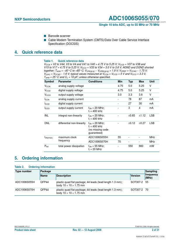
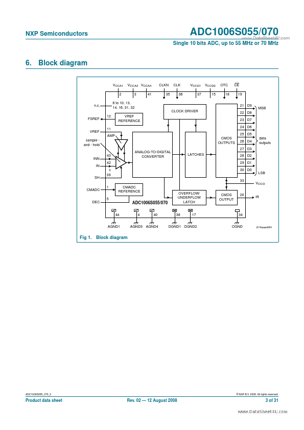
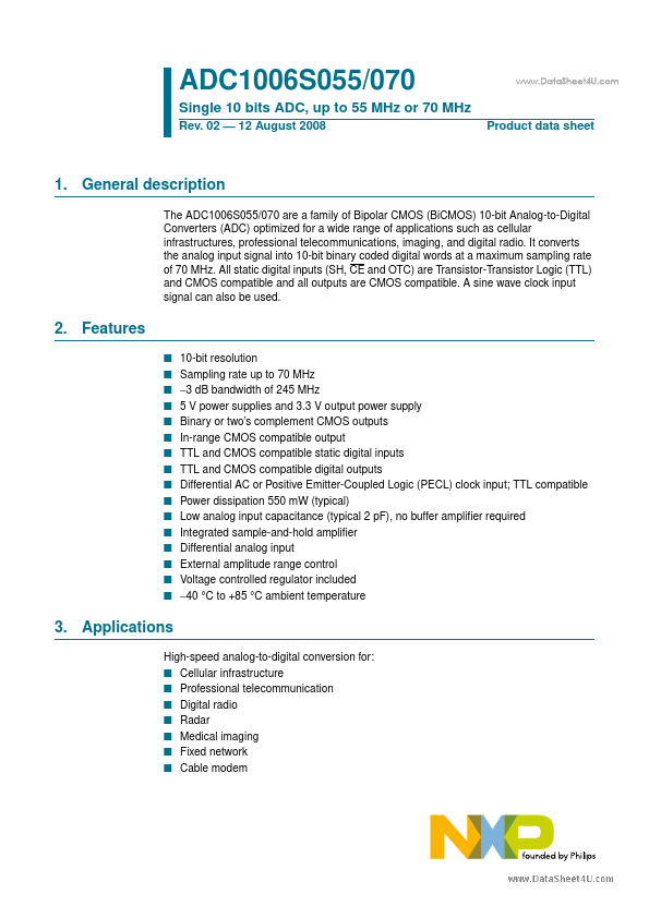
The ADC1006S055/070 are a family of Bipolar CMOS (BiCMOS) 10-bit Analog-to-Digital Converters (ADC) optimized for a wide range of applications such as cellular infrastructures, professional telecommunications, imaging, and digital radio.
| Part number | ADC1006S070 |
|---|---|
| Manufacturer | NXP Semiconductors |
| File Size | 431.05 KB |
| Description | Single 10-bits ADC |
| Datasheet |
ADC1006S070 Datasheet
|
|
|
|
Note: Below is a high-fidelity text extraction (approx. 800 characters) for ADC1006S070. For precise diagrams, and layout, please refer to the original PDF.
ADC1006S055/070 Single 10 bits ADC, up to 55 MHz or 70 MHz Rev. 02 — 12 August 2008 www.DataSheet4U.com Product data sheet 1. General description The ADC1006S055/070 are ...
| Part Number | Description |
|---|---|
| ADC1006S055 | Single 10-bits ADC |
| ADC1002S020 | Single 10 bits ADC |
| ADC1003S030 | Single 10-bits ADC |
| ADC1003S040 | Single 10-bits ADC |
| ADC1003S050 | Single 10-bits ADC |
| ADC1004S030 | Single 10-bits ADC |
| ADC1004S040 | Single 10-bits ADC |
| ADC1004S050 | Single 10-bits ADC |
| ADC1005S060 | Single 10 bits ADC |
| ADC1010S | Single 10-bit ADC |