Datasheet4U Logo Datasheet4U.com

X9409 - Quad Digitally Controlled Potentiometers

Description

PIN # 11 1 14, 2, 23, 12 21, 4, 9, 16, 20, 3, 10, 17 22, 5, 8, 15 24 19 6 7, 13, 18 FN8192 Rev.6.00 Sep 3, 2015 SYMBOL SCL SDA A0, A1, A2, A3 VH0/RH0, VH1/RH1, VH2/RH2, VH3/RH3, VL0/RL0, VL1/RL1, VL2/RL2, VL3/RL3 VW0/RW0, VW1/RW1, VW2/RW2, VW3/RW3 WP VCC VSS NC DESCRIPTION Serial Clock Serial Dat

Features

  • Four potentiometers per package.
  • 64 resistor taps.
  • 2-wire serial interface for write, read and transfer operations of the potentiometer.
  • 50Ω wiper resistance, typical at 5V.
  • Four nonvolatile data registers for each potentiometer.
  • Nonvolatile storage of multiple wiper position.
  • Power-on recall. Loads saved wiper position on power-up standby current < 1µA typical.
  • System VCC: 2.7V operation.
  • 10kΩ end-to-end resistanc.

📥 Download Datasheet

Full PDF Text Transcription

Click to expand full text
OBSOLETE PRODUCT DATASHEET NO RECOMMENDED REPLACEMENT contact our Technical Support Center at X9409 1-888-INTERSIL or www.intersil.com/tsc FN8192 Low Noise/Low Power/2-Wire Bus Quad Digitally Controlled Potentiometers Rev.6.00 (XDCP) Sep 3, 2015 
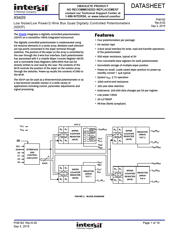
The X9409 integrates 4 digitally controlled potentiometers (XDCP) on a monolithic CMOS integrated microcircuit. The digitally controlled potentiometer is implemented using 63 resistive elements in a series array. Between each element are tap points connected to the wiper terminal through switches. The position of the wiper on the array is controlled by the user through the 2-wire bus interface.
Published: |