Datasheet4U Logo Datasheet4U.com

HIP5011 - 7V/ 17A SynchroFET Complementary Drive Synchronous Half-Bridge

Description

SYMBOL VCC VIN PHASE PWM (HIP5010) PWM (HIP5011) GND DESCRIPTION Positive supply to control logic and gate drivers.

De-couple this pin to GND.

FET Switch Input Voltage.

Features

  • ensure easy start-up. First, the supply currents stay below specification as the supply voltages ramp up; no unexpected surges occur that might perturb a soft-start or deplete a charge-pump. Second, any power-up sequence of the VCC, VIN , or PWM pins can be used without causing large currents. Third, the chip operates when VCC is greater than 2V so VCC can be created from a charge pump powered from VIN. Features.
  • Complementary Drive, Half-Bridge Power NMOS.
  • Use With Low-Cost S.

📥 Download Datasheet

Datasheet Details

Part number HIP5011
Manufacturer Intersil (Renesas)
File Size 38.37 KB
Description 7V/ 17A SynchroFET Complementary Drive Synchronous Half-Bridge
Datasheet download datasheet HIP5011 Datasheet

Full PDF Text Transcription

Click to expand full text
HIP5010, HIP5011 Data Sheet March 1996 File Number 4029.5 
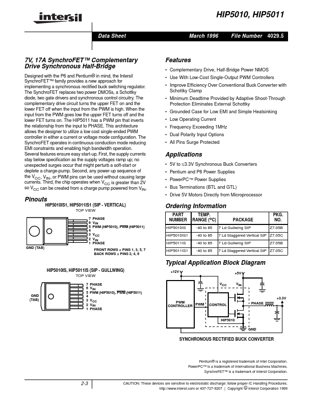
7V, 17A SynchroFET™ Complementary Drive Synchronous Half-Bridge 
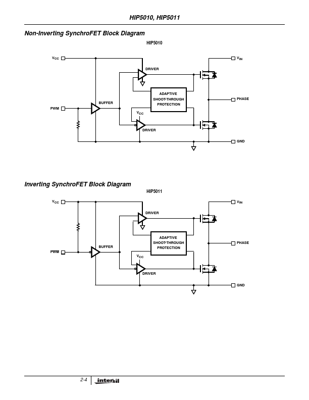
Designed with the P6 and Pentium® in mind, the Intersil SynchroFET™ family provides a new approach for implementing a synchronous rectified buck switching regulator. The SynchroFET replaces two power DMOSs, a Schottky diode, two gate drivers and synchronous control circuitry. The complementary drive circuit turns the upper FET on and the lower FET off when the input from the PWM is high. When the input from the PWM goes low the upper FET turns off and the lower FET turns on. The HIP5011 has a PWM pin that inverts the relationship from the input to PHASE.
Published: |