Click to expand full text
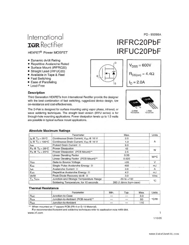
PD - 95098A
IRFRC20PbF IRFUC20PbF
• Lead-Free
www.irf.com
1
1/10/05
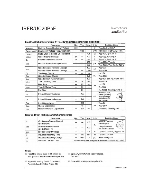
IRFR/UC20PbF
2
www.irf.com
IRFR/UC20PbF
www.irf.com
3
IRFR/UC20PbF
4
www.irf.com
IRFR/UC20PbF
www.irf.com
5
IRFR/UC20PbF
6
www.irf.com
IRFR/UC20PbF
Peak Diode Recovery dv/dt Test Circuit
+
Circuit Layout Considerations • Low Stray Inductance • Ground Plane • Low Leakage Inductance Current Transformer
+ +
-
• dv/dt controlled by RG • ISD controlled by Duty Factor "D" • D.U.T. - Device Under Test
+ -
*
Reverse Polarity for P-Channel ** Use P-Channel Driver for P-Channel Measurements
Driver Gate Drive P.W. Period D=
P.W. Period VGS=10V
D.U.T. ISD Waveform Reverse Recovery Current Body Diode Forward Current di/dt D.U.T.
 IRFUC20PBF Datasheet