The following content is an automatically extracted verbatim text
from the original manufacturer datasheet and is provided for reference purposes only.
View original datasheet text
PD - 97104
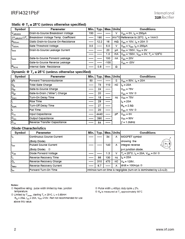
IRFI4321PbF
Applications l Motion Control Applications l High Efficiency Synchronous Rectification in SMPS l Uninterruptible Power Supply l Hard Switched and High Frequency Circuits Benefits l Low RDSON Reduces Losses l Low Gate Charge Improves the Switching Performance l Improved Diode Recovery Improves Switching & EMI Performance l 30V Gate Voltage Rating Improves Robustness l Fully Characterized Avalanche SOA
HEXFET® Power MOSFET
VDSS RDS(on) typ. max. ID
D
150V 12.
 IRFI4321PBF Datasheet