Datasheet4U Logo Datasheet4U.com

IXFK69N30P - PolarHT HiPerFET Power MOSFET

Download the IXFK69N30P datasheet PDF. This datasheet also covers the IXFH69N30P variant, as both devices belong to the same polarht hiperfet power mosfet family and are provided as variant models within a single manufacturer datasheet.

Features

  • z z 1.6 mm (0.062 in. ) from case for 10 s Mounting torque TO-247 TO-264 300 1.13/10 Nm/lb. in. 6 10 g g z z International standard packages Unclamped Inductive Switching (UIS) rated Low package inductance - easy to drive and to protect Fast intrinsic diode Symbol Test Conditions (TJ = 25°C, unless otherwise specified) VDSS VGS(th) IGSS IDSS RDS(on) VGS = 0 V, ID = 250 µA VDS = VGS, ID = 250µA VGS = ±20 VDC, VDS = 0 VDS = VDSS VGS = 0 V TJ = 125°C Characteristic Values Min. Typ. Max. 300 2.

📥 Download Datasheet

Note: The manufacturer provides a single datasheet file (IXFH69N30P_IXYS.pdf) that lists specifications for multiple related part numbers.

Full PDF Text Transcription

Click to expand full text
PolarHT HiPerFET Power MOSFET TM IXFH69N30P IXFK69N30P N-Channel Enhancement Mode Fast Intrinsic Diode RDS(on) trr VDSS ID25 = 300 V = 69 A = 49 mΩ ≤ 200 ns www.DataSheet4U.com 
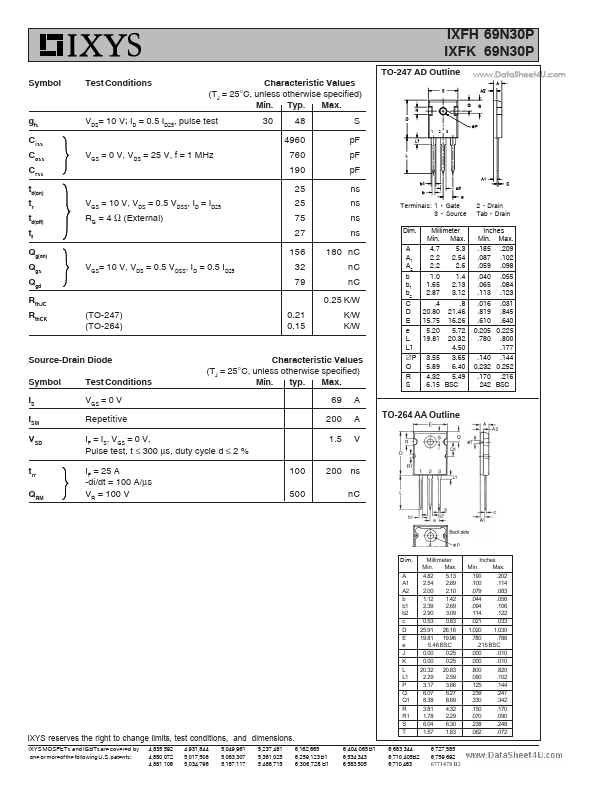
Symbol VDSS VDGR VGS VGSM ID25 IDM IAR EAR EAS dv/dt PD TJ TJM Tstg TL Md Weight Test Conditions TJ = 25°C to 150°C TJ = 25°C to 150°C; RGS = 1 MΩ Continuous Transient TC = 25°C TC = 25°C, pulse width limited by TJM TC = 25°C TC = 25°C TC = 25°C IS ≤ IDM, di/dt ≤ 100 A/µs, VDD ≤ VDSS, TJ ≤ 150°C, RG = 4 Ω TC = 25°C Maximum Ratings 300 300 ± 20 ± 30 69 200 69 50 1.5 10 500 -55 ... +150 150 -55 ... +150 V V V V A A A mJ J V/ns W °C °C °C °C TO-247 (IXFH) G D (TAB) D S TO-264 (IXFK) G D D (TAB) S D = Drain TAB = Drain G = Gate S = Source Features z z 1.6 mm (0.062 in.
Published: |