Datasheet4U Logo Datasheet4U.com

IXFT80N085 - Power MOSFET

Datasheet Summary

Features

  • Symbol Test Conditions Characteristic Values (TJ = 25°C, unless otherwise specified) min. typ. max. 85 2.0 4.0 ±100 TJ = 25°C TJ = 125°C 50 1 9 V V nA mA mA mW Advantages.
  • Easy to mount.
  • Space savings.
  • High power density.
  • International standard packages.
  • Low RDS (on).
  • Rated for unclamped Inductive load switching (UIS).
  • Molding epoxies meet UL 94 V-0 flammability classification VDSS VGS(th) IGSS IDSS RDS(on) VGS = 0 V, ID = 1 mA VDS.

📥 Download Datasheet

Datasheet preview – IXFT80N085

Datasheet Details

Part number IXFT80N085
Manufacturer IXYS Corporation
File Size 54.03 KB
Description Power MOSFET
Datasheet download datasheet IXFT80N085 Datasheet
Additional preview pages of the IXFT80N085 datasheet.
Other Datasheets by IXYS Corporation

Full PDF Text Transcription

Click to expand full text
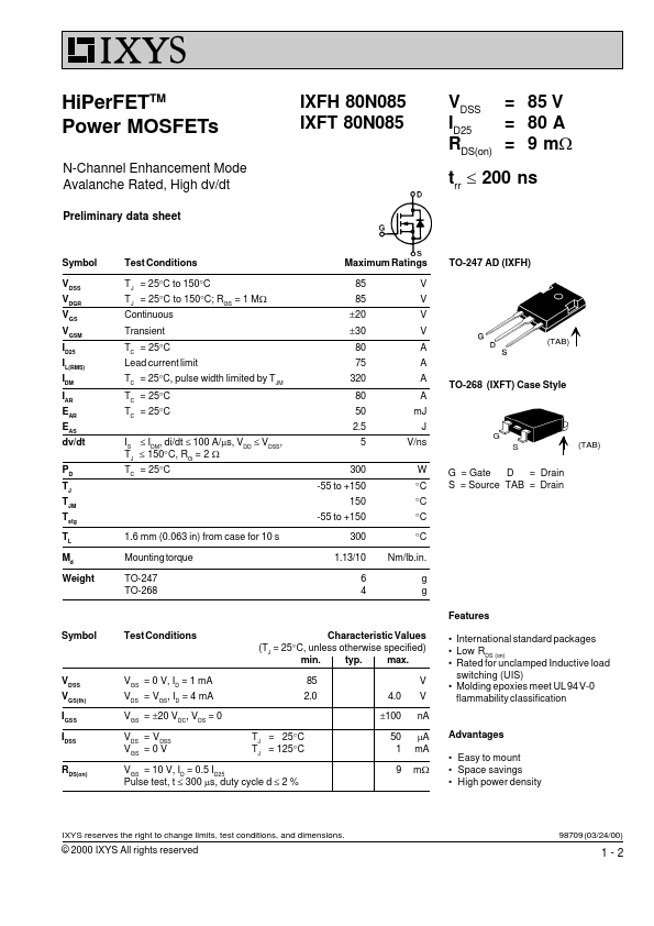
HiPerFETTM Power MOSFETs N-Channel Enhancement Mode Avalanche Rated, High dv/dt Preliminary data sheet IXFH 80N085 IXFT 80N085 VDSS = 85 V = 80 A ID25 RDS(on) = 9 mW trr £ 200 ns Symbol VDSS VDGR VGS VGSM ID25 IL(RMS) IDM IAR EAR EAS dv/dt PD TJ TJM Tstg TL Md Weight Test Conditions TJ = 25°C to 150°C TJ = 25°C to 150°C; RGS = 1 MW Continuous Transient TC = 25°C Lead current limit TC = 25°C, pulse width limited by TJM TC = 25°C TC = 25°C IS £ IDM, di/dt £ 100 A/ms, VDD £ VDSS, TJ £ 150°C, RG = 2 W TC = 25°C Maximum Ratings 85 85 ±20 ±30 80 75 320 80 50 2.5 5 300 -55 to +150 150 -55 to +150 V V V V A A A A mJ J V/ns W °C °C °C °C Nm/lb.in. g g
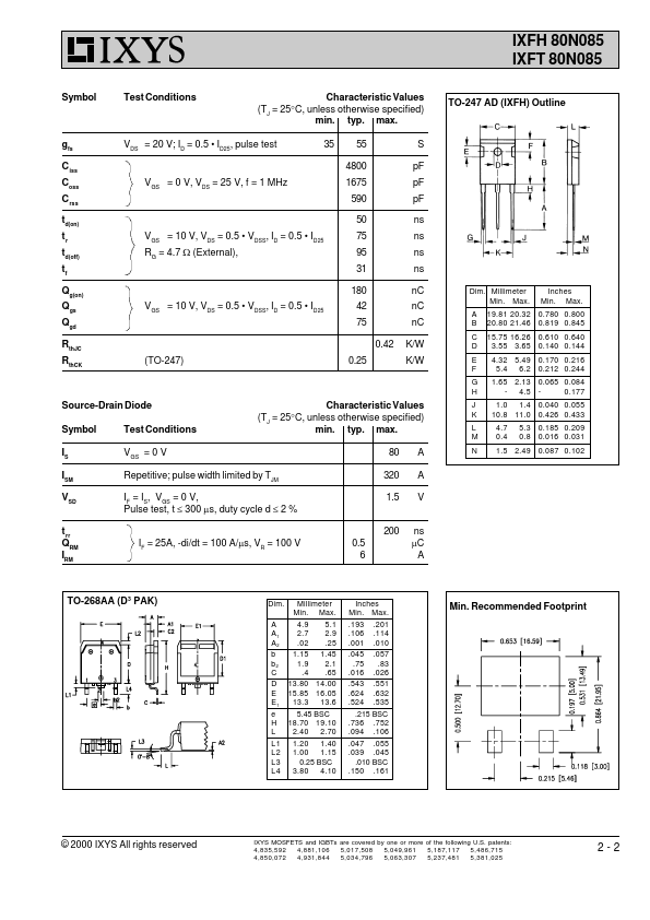
 TO-247 AD (IXFH) (TAB) TO-268 (IXFT) Case Style G S (TAB) G = Gate D = Drain S = Source TAB = Drain 1.6 mm (0.
Published: |