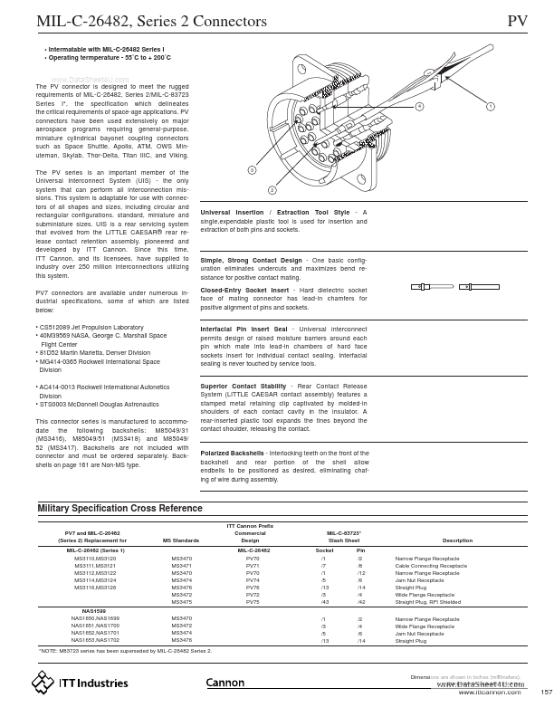
a stamped metal retaining clip captivated by molded-in shoulders of each contact cavity in the insulator. A rear-inserted plastic tool expands the tines beyond the contact shoulder, releasing the contact. Polarized Backshells - Interlocking teeth on the front of the backshell and rear portion of the shell allow endbells to be positioned as desired, eliminating chafing of wire during assembly. Military Specification Cross Reference
PV7 and MIL-C-26482 (Series 2) Replacement for MIL-C-26482 (Ser.
Full PDF Text Transcription for MS3476L18-32SW (Reference)
Note: Below is a high-fidelity text extraction (approx. 800 characters) for
MS3476L18-32SW. For precise diagrams, and layout, please refer to the original PDF.
MIL-C-26482, Series 2 Connectors • Intermatable with MIL-C-26482 Series I • Operating termperature - 55˚C to + 200˚C PV www.DataSheet4U.com The PV connector is designed t...
View more extracted text
55˚C to + 200˚C PV www.DataSheet4U.com The PV connector is designed to meet the rugged requirements of MIL-C-26482, Series 2/MIL-C-83723 Series I*, the specification which delineates the critical requirements of space-age applications. PV connectors have been used extensively on major aerospace programs requiring general-purpose, miniature cylindrical bayonet coupling connectors such as Space Shuttle, Apollo, ATM, OWS Minuteman, Skylab, Thor-Delta, Titan IIIC, and Viking. The PV series is an important member of the Universal Interconnect System (UIS) - the only system that can perform all interconnection missions.
 MS3476L18-32SW Datasheet