Click to expand full text
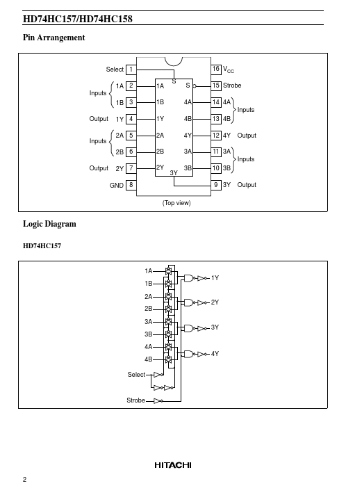
HD74HC157/HD74HC158
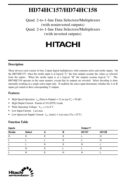
Quad. 2-to-1-line Data Selectors/Multiplexers (with noninverted outputs) Quad. 2-to-1-line Data Selectors/Multiplexers (with inverted outputs)
Description
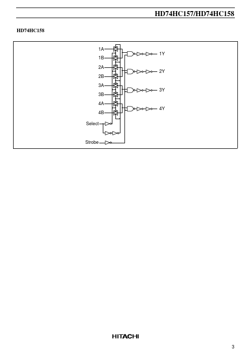
These devices each consist of four 2-input digital multiplexers with common select and strobe inputs. On the HD74HC157, when the strobe input is at logical “L” the four outputs assume the values as selected from the inputs. When the strobe input is at a logical “H” the outputs assume logical “L”. The HD74HC158 operates in the same manner, except that its outputs are inverted. Select decoding is done internally resulting in a single select input only. If enabled, the select input determines whether the A or B inputs get routed to their corresponding Y outputs.
 HD74HC158 Datasheet