Download the SS33F datasheet PDF.
This datasheet also covers the SS32F variant, as both devices belong to the same schottky barrier rectifiers family and are provided as variant models within a single manufacturer datasheet.
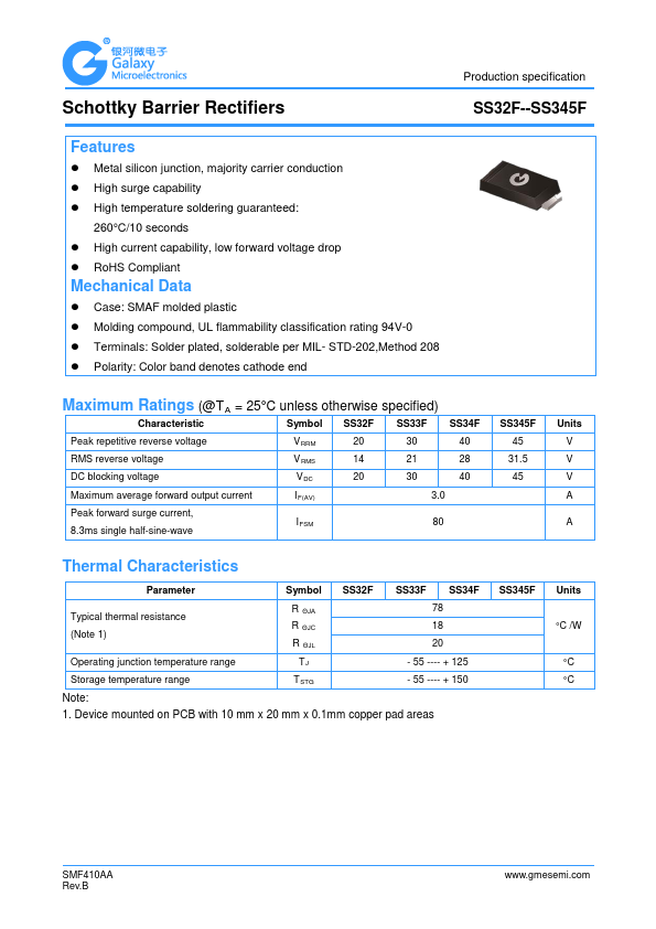
Key Features
Metal silicon junction, majority carrier conduction.
High surge capability.
High temperature soldering guaranteed:
260°C/10 seconds.
High current capability, low forward voltage drop.
RoHS Compliant
Mechanical Data.
Case: SMAF molded plastic.
Molding compound, UL flammability classification rating 94V-0.
Terminals: Solder plated, solderable per MIL- STD-202,Method 208.
Polarity: Color band denotes cathode end
Maximum Ratings (@TA = 25°C unless other.
Note: Below is a high-fidelity text extraction (approx. 800 characters) for
SS33F. For precise diagrams, and layout, please refer to the original PDF.
Schottky Barrier Rectifiers Production specification SS32F--SS345F Features Metal silicon junction, majority carrier conduction High surge capability High temperatu...
View more extracted text
, majority carrier conduction High surge capability High temperature soldering guaranteed: 260°C/10 seconds High current capability, low forward voltage drop RoHS Compliant Mechanical Data Case: SMAF molded plastic Molding compound, UL flammability classification rating 94V-0 Terminals: Solder plated, solderable per MIL- STD-202,Method 208 Polarity: Color band denotes cathode end Maximum Ratings (@TA = 25°C unless otherwise specified) Characteristic Symbol SS32F SS33F SS34F Peak repetitive reverse voltage V RRM 20 30 40 RMS reverse voltage V RMS 14 21 28 DC blocking voltage V DC 20 30 40 Maximum average for
 SS33F Datasheet