Datasheet Details
| Part number | 74S175 |
|---|---|
| Manufacturer | Fairchild (onsemi) |
| File Size | 142.59 KB |
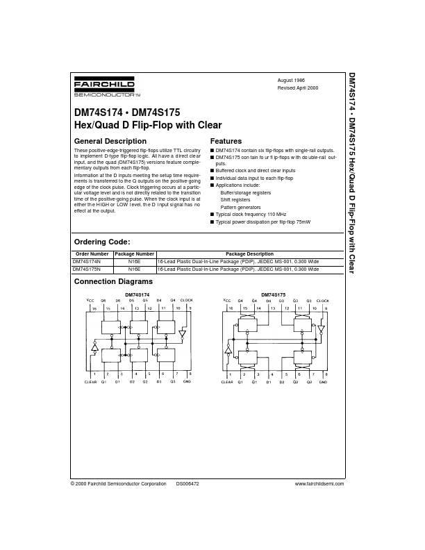
| Description | Hex/Quad D Flip-Flop |
| Datasheet |
 74S175 Datasheet 74S175 Datasheet
|
|
|
These positive-edge-triggered flip-flops utilize TTL circuitry to implement D-type flip-flop lo gic.
All h ave a d irect cle ar input, and the quad (DM74S175) versions feature complementary outputs from each flip-flop.
| Part number | 74S175 |
|---|---|
| Manufacturer | Fairchild (onsemi) |
| File Size | 142.59 KB |
| Description | Hex/Quad D Flip-Flop |
| Datasheet |
74S175 Datasheet
|
|
|
|
| Part Number | Description | Manufacturer |
|---|---|---|
| 74S10 | STTL type three 3-input NAND gate | TW |
| 74S133 | 13-Input NAND Gate | SYC |
| 74S134 | 12-INPUT POSITIVE-NAND GATES | Fairchild |
| 74S134 | 12-INPUT POSITIVE-NAND GATES | Signetics |
| 74S135 | Quad Exclusive OR/NOR Gate | Fairchild |
| Part Number | Description |
|---|---|
| 74S112 | Dual Negative-Edge-Triggered Master-Slave J-K Flip-Flop |
| 74S138 | Decoder/Demultiplexer |
| 74S139 | Decoder/Demultiplexer |
| 74S140 | Dual 4-Input NSND Line Driver |
| 74S153 | Dual 1-of-4 Line Data Selector/Multiplexer |
The following content is an automatically extracted verbatim text from the original manufacturer datasheet and is provided for reference purposes only.