Datasheet4U Logo Datasheet4U.com

PBD35171 - Stepper Motor Drive Circuit

General Description

PBD 3517/1 is a bipolar, monolithic, integrated circuit, intended to drive a stepper motor in a unipolar, bilevel way.

One PBD 3517/1 and a minimum of external components form a complete control and drive unit for LS-TTL- or microprocessor-controlled stepper motor system for currents up to 500mA.

Key Features

  • Complete driver and phase logic on chip.
  • 2 x 350 mA continuous-output current.
  • Half- and full-step mode generation.
  • LS-TTL-compatible inputs.
  • Bilevel drive mode for high step rates.
  • Voltage-doubling drive possibilities.
  • Half-step position-indication output.
  • Minimal RFI.
  • 16-pin plastic DIP package or 16 pin small outline wide body VCC VSS PQR LB STEP PB2 INH OA OB PA2 PA1 GND 16-pin plastic DIP 16-pin SO (w.

📥 Download Datasheet

Datasheet Details

Part number PBD35171
Manufacturer Ericsson
File Size 135.69 KB
Description Stepper Motor Drive Circuit
Datasheet download datasheet PBD35171 Datasheet

Full PDF Text Transcription (Reference)

The following content is an automatically extracted verbatim text from the original manufacturer datasheet and is provided for reference purposes only.

View original datasheet text
February 1999 PBD 3517/1 Stepper Motor Drive Circuit
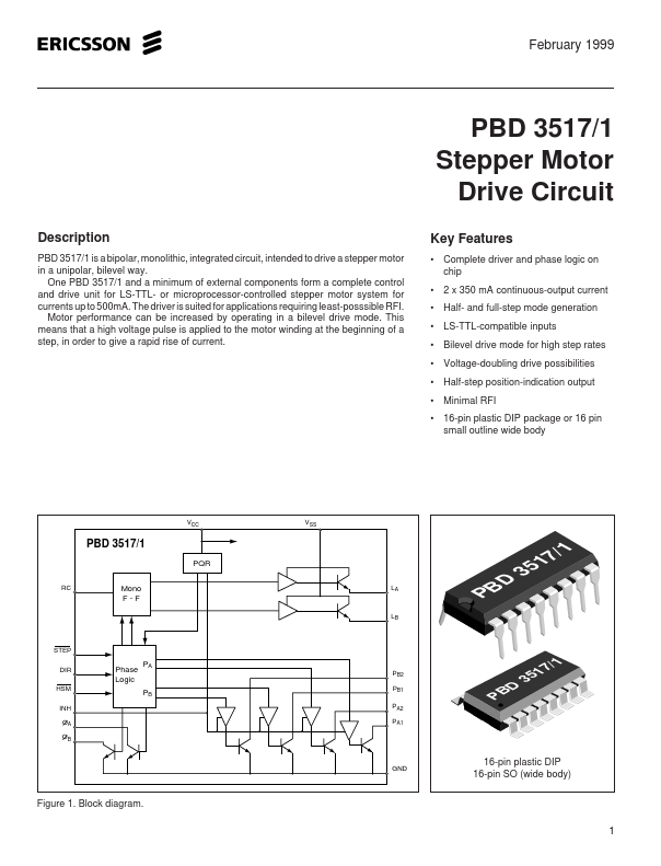
 Description PBD 3517/1 is a bipolar, monolithic, integrated circuit, intended to drive a stepper motor in a unipolar, bilevel way. One PBD 3517/1 and a minimum of external components form a complete control and drive unit for LS-TTL- or microprocessor-controlled stepper motor system for currents up to 500mA. The driver is suited for applications requiring least-posssible RFI. Motor performance can be increased by operating in a bilevel drive mode. This means that a high voltage pulse is applied to the motor winding at the beginning of a step, in order to give a rapid rise of current.