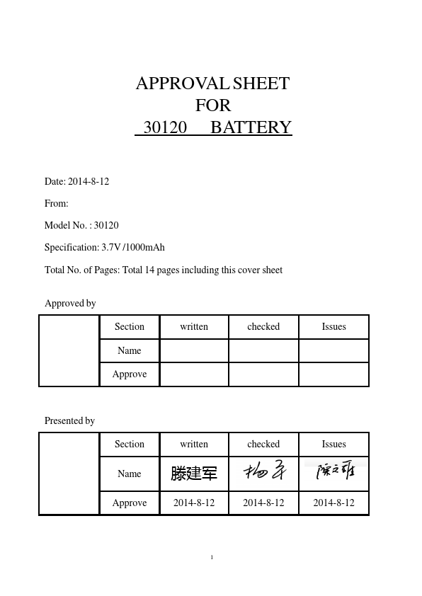
30120
Description
A-1-2. PCM AND Board Connection A-1-3. Application Note
Assembly Diagram A-1-4. Schematic A-1-5. PCM BOM
A-1-1.General Description
1. The protection module adopts the DW01 SOT-23-6 to monitor LI-Ion cell for over-voltage, under-voltage, over-charge current and over-discharge current.
2. External N-FET AO8205 will be driven to cut off the loop of charge and discharge if any abnormal condition occurs.
A-1-2 PCM and Board Connection
BOTTOM
Board Connection
Pin
Description
B+ Connect to Positive terminal of cell1
B- Connect to negative terminal of cell1
P+ Connect to Camcorder +/Charger +
P- Connect to Camcorder -/ Charger +
A-1-3.Application Note
Assembly diagram
A-1-4.Schematic
10KNTC
1 0
A-1-5.BOM
No.
Name
Resistor
Resistor
Resistor
Capacitor
Function DB PDA011 V1.0 DW01 SOT-23-6 AO8205 TSSOP-8 100Ω±5% 0603 1KΩ±5% 0603 10K ±5% NTC 0603 0.1u F 50V Y5V M 0603
Unit...