Download the KBP206-G datasheet PDF.
This datasheet also covers the KBP200-G variant, as both devices belong to the same silicon bridge rectifiers family and are provided as variant models within a single manufacturer datasheet.
Key Features
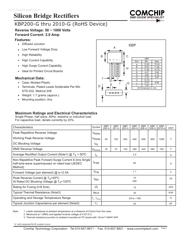
Diffused Junction Low Forward Voltage Drop High Reliability High Current Capability High Surge Current Capability Ideal for Printed Circuit Boards H J D E I G B + ~ ~ A C
KBP Min. Max Dim 14.22 15.24 A B 11.68 10.67 C 11.68 12.70 D 4.57 5.08 3.60 4.10 E 2.16 2.67 G 12.70 H 0.88 0.76 J 1.52 I All Dimension in mm
KBP
Mechanical Data:
Case: Molded Plastic Terminals: Plated Leads Solderable Per MIL STD-202, Method 208 Weight: 1.7 grams (approx. ) Mounting position: Any
Maximum Ratings and Electri.
Full PDF Text Transcription for KBP206-G (Reference)
Note: Below is a high-fidelity text extraction (approx. 800 characters) for
KBP206-G. For precise diagrams, and layout, please refer to the original PDF.
~ 1000 Volts Forward Current: 2.0 Amp Features: Diffused Junction Low Forward Voltage Drop High Reliability High Current Capability High Surge Current Capability Ideal for Printed Circuit Boards H J D E I G B + ~ ~ A C KBP Min. Max Dim 14.22 15.24 A B 11.68 10.67 C 11.68 12.70 D 4.57 5.08 3.60 4.10 E 2.16 2.67 G 12.70 H 0.88 0.76 J 1.52 I All Dimension in mm KBP Mechanical Data: Case: Molded Plastic Terminals: Plated Leads Solderable Per MIL STD-202, Method 208 Weight: 1.7 grams (approx.) Mounting position: Any Maximum Ratings and Electrical Characteristics Single Phase, half wave, 60Hz, resistive or inductive load. For c
 KBP206-G Datasheet