Click to expand full text
Advisory July 1998
LH1465AB/AAE ISDN dc Termination IC Data Sheet Advisory
Application Circuit
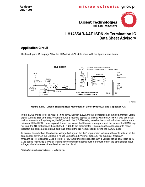
Replace Figure 11 on page 10 of the LH1465AB/AAE data sheet with the figure shown below.
MLT CIRCUIT
C15 1.0 µF R11 137 Ω
(PLACE THIS CAPACITOR AS CLOSE AS POSSIBLE TO THE LH1465) LH1465AB 8 TC PR+ 7 RS T U3 6 PD R 5 COM PR– R14 1.1 kΩ 2W
+5 V R10 10 kΩ 8 6 5 R9
R8 17.8 kΩ SCNT1 OPTOIN PIN
U2
R12 137 Ω 2 3 CA 1.0 µF ZD
1 2 3 4
R15 1.1 kΩ 2W RING TIP
7
HCPL-0701
2.2 MΩ
FOR NORTH AMERICAN APPLICATIONS ONLY
5-7034(C)
Figure 1. MLT Circuit Showing New Placement of Zener Diode (ZD) and Capacitor (CA) In the ILOSS mode (refer to ANSI T1.601 1992, Section 6.5.2), the NT generates a scrambled, framed, 2B1Q signal such as SN1 and SN2.
 LH1465AB Datasheet