Datasheet Details
| Part number | SN74HC109N |
|---|---|
| Manufacturer | Texas Instruments |
| File Size | 1.67 MB |
| Description | DUAL J-K POSITIVE-EDGE-TRIGGERED FLIP-FLOPS |
| Datasheet |
 SN74HC109N Datasheet SN74HC109N Datasheet
|
|
|
Download the SN74HC109N datasheet PDF. This datasheet also covers the SN74HC109 variant, as both devices belong to the same dual j-k positive-edge-triggered flip-flops family and are provided as variant models within a single manufacturer datasheet.
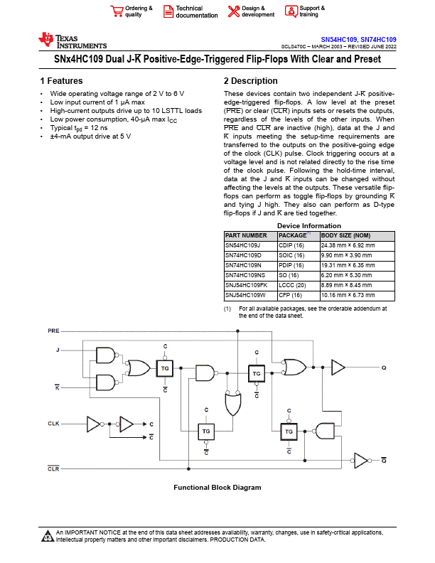
These devices contain two independent J-K positiveedge-triggered flip-flops.
A low level at the preset (PRE) or clear (CLR) inputs sets or resets the outputs, regardless of the levels of the other inputs.
| Part number | SN74HC109N |
|---|---|
| Manufacturer | Texas Instruments |
| File Size | 1.67 MB |
| Description | DUAL J-K POSITIVE-EDGE-TRIGGERED FLIP-FLOPS |
| Datasheet |
SN74HC109N Datasheet
|
|
|
|
| Part Number | Description | Manufacturer |
|---|---|---|
| SN74HC182 | FUNCTION LOOK AHEAD CARRY GENERATOR | ST Microelectronics |
| SN74HC06 | Hex Inverter | Lingxing Microelectronics |
| SN74HC423 | DUAL RETRIGGERABLE MONOSTABLE MULTIVIBRATOR | ST Microelectronics |
| SN74HCT06 | Hex Inverter | Lingxing Microelectronics |
| SN74H74N | Dual D-Type Flip-Flop | ETC |
| Part Number | Description |
|---|---|
| SN74HC109 | DUAL J-K POSITIVE-EDGE-TRIGGERED FLIP-FLOPS |
| SN74HC10 | Triple 3-Input NAND Gates |
| SN74HC10-EP | TRIPLE 3-INPUT POSITIVE-NAND GATE |
| SN74HC10-Q1 | TRIPLE 3-INPUT POSITIVE-NAND GATE |
| SN74HC10D | Triple 3-Input NAND Gates |
The following content is an automatically extracted verbatim text from the original manufacturer datasheet and is provided for reference purposes only.