Datasheet4U Logo Datasheet4U.com

UF5407G - (UF5400G - UF5408G) 3.0A GLASS PASSIVATED ULTRAFAST DIODE

Download the UF5407G datasheet PDF. This datasheet also covers the UF5408G_Won variant, as both devices belong to the same (uf5400g - uf5408g) 3.0a glass passivated ultrafast diode family and are provided as variant models within a single manufacturer datasheet.

Features

  • ! ! ! ! ! Glass Passivated Die Construction Low Forward Voltage Drop High Current Capability High Reliability High Surge Current Capability A B A Mechanical Data ! ! ! ! ! ! ! Case: DO-201AD, Molded Plastic Terminals: Plated Leads Solderable per MIL-STD-202, Method 208 Polarity: Cathode Band Weight: 1.2 grams (approx. ) Mounting Position: Any Marking: Type Number Lead Free: For RoHS / Lead Free Version, Add “-LF” Suffix to Part Number, See Page 4 D DO-201AD Dim Min Max 25.4.
  • A 7.20 9.50.

📥 Download Datasheet

Note: The manufacturer provides a single datasheet file (UF5408G_Won-TopElectronics.pdf) that lists specifications for multiple related part numbers.

Datasheet Details

Part number UF5407G
Manufacturer Won-Top Electronics
File Size 76.81 KB
Description (UF5400G - UF5408G) 3.0A GLASS PASSIVATED ULTRAFAST DIODE
Datasheet download datasheet UF5407G Datasheet

Full PDF Text Transcription (Reference)

The following content is an automatically extracted verbatim text from the original manufacturer datasheet and is provided for reference purposes only.

View original datasheet text
WTE POWER SEMICONDUCTORS
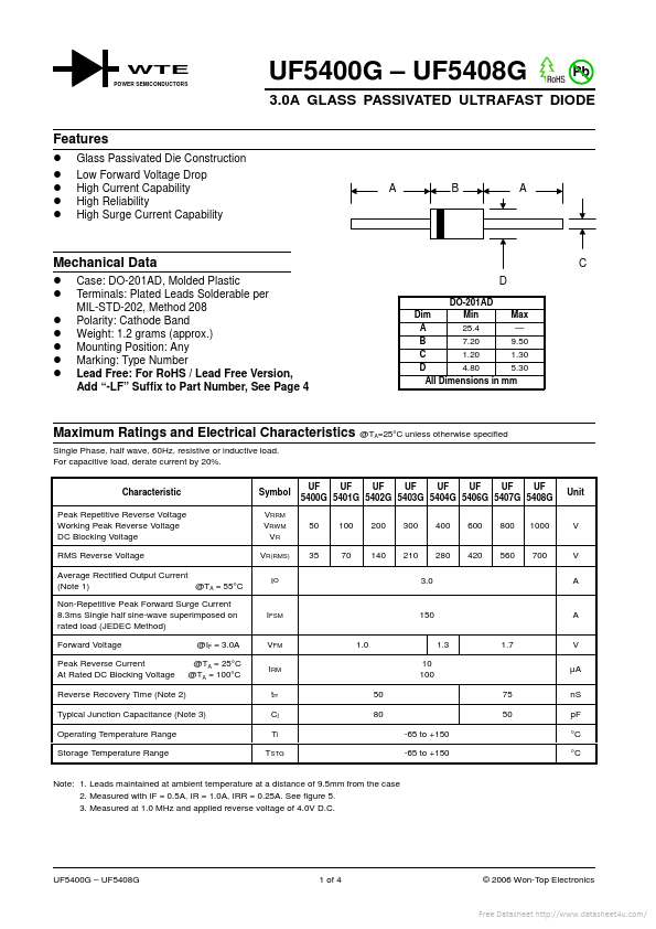
 UF5400G – UF5408G Pb 3.0A GLASS PASSIVATED ULTRAFAST DIODE Features ! ! ! ! ! Glass Passivated Die Construction Low Forward Voltage Drop High Current Capability High Reliability High Surge Current Capability A B A Mechanical Data ! ! ! ! ! ! ! Case: DO-201AD, Molded Plastic Terminals: Plated Leads Solderable per MIL-STD-202, Method 208 Polarity: Cathode Band Weight: 1.2 grams (approx.) Mounting Position: Any Marking: Type Number Lead Free: For RoHS / Lead Free Version, Add “-LF” Suffix to Part Number, See Page 4 D DO-201AD Dim Min Max 25.4 — A 7.20 9.50 B 1.20 1.30 C 4.80 5.30 D All Dimensions in mm C Maximum Ratings and Electrical Characteristics 
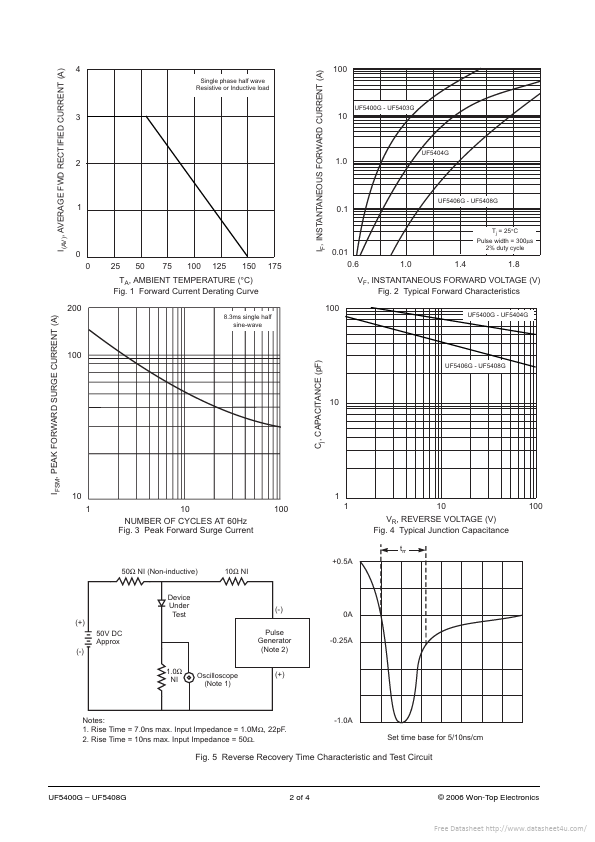
Single Phase, half wave, 60Hz, resistive or inductive load. For capacitive load, derate current by 20%.
Published: |