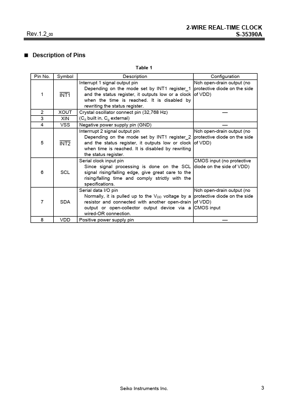
Description
of Pins
Table 1 Pin No.Symbol Description Interrupt 1 signal output pin Depending on the mode set by INT1 register_1 and the status register, it outputs low or a clock when the time is reached.It is disabled by rewriting the status register.Crystal oscillator connect pin (32,768 Hz) (Cd built in, Cg external) Negative power supply pin (GND) Interrrupt 2 signal output pin Depending on the mode set by INT1 register_2 and the status register, it outputs low or clock when time is reached.It is d
Features
- Low current consumption: 0.25 µA typ. (VDD = 3.0 V, Ta = 25°C) Wide operating voltage range: 1.3 to 5.5 V Minimum time keeping operation voltage: 1.1 V Built-in clock adjustment function Built-in free user register 2-wire (I2C-BUS).
- 1 CPU interface Built-in alarm interrupter Built-in flag generator at power down or power on Auto calendar up to the year 2099, automatic leap.
 S35-390-A.pdf