Download the HGTP7N60A4D datasheet PDF.
This datasheet also covers the HGTG7N60A4D variant, as both devices belong to the same n-channel igbt family and are provided as variant models within a single manufacturer datasheet.
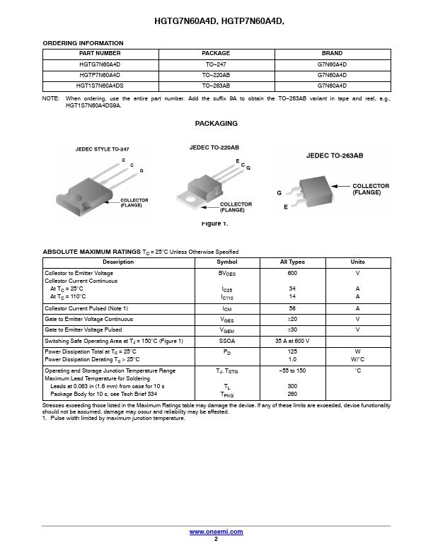
Description
Symbol
All Types
Units
Collector to Emitter Voltage Collector Current Continuous
At TC = 25°C At TC = 110°C
BVCES
600
V
IC25
34
A
IC110
14
A
Collector Current Pulsed (Note 1) Gate to Emitter Voltage Continuous Gate to Emitter Voltage Pulsed Switching Safe Operating Area at TJ = 150°C (
Features
- of MOSFETs and bipolar transistors. These devices have the high input impedance of a MOSFET and the low on.
- state conduction loss of a bipolar transistor. The much lower on.
- state voltage drop varies only moderately between 25°C and 150°C. The IGBT used is the development type TA49331. The diode used in anti.
- parallel is the development type TA49370.
This IGBT is ideal for many high voltage switching.
 HGTP7N60A4D Datasheet