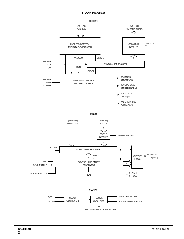
Description
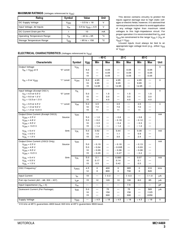
A0
A6 Address Inputs
These inputs are the address setting pins which contain the address match for the received signal.Pins A0
A6 have on
chip pull
up resistors.
C6 Command Word
These pins are the readout of the general
purpose command word which is the second word of the received signal.
C6).
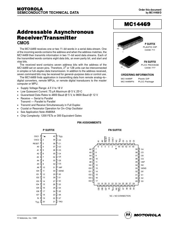
Features
- n at the center of a receive clock period. The start bit is followed by eight data bits. Seven of the bits are compared against states of the address of the particular circuit (A0.
- A6). Address is latched 31 clock cycles after the end of the start bit of the incoming address. The eighth bit signifies an address word “1” or a command word “0”. Next, a parity bit is received and checked by the internal logic for even parity. Finally a stop bit is received. At the completion of the cycle i.
 MC14469P_MotorolaInc.pdf