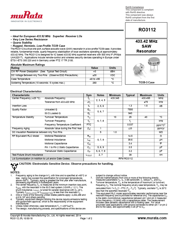
RoHS Compliance
This component is compliant
with RoHS directive.
This component was always
RoHS compliant from the first
date of manufacture.
• Ideal for European 433.92 MHz Superhet Receiver LOs
• Very Low Series Resistance
• Quartz Stability
• Rugged, Hermetic, Low-Profile TO39 Case
The RO3112 is a true one-port, surface-acoustic-wave (SAW) resonator in a low-profile TO39 case. It provides
reliable, fundamental-mode, quartz frequency stabilization of local oscillators operating at approximately
433.42 MHz. The RO2112 is designed for IC based 433.92 MHz superhet receivers with 500 kHz IF (Philips
UAA3201T). Applications include remote-control and wireless security devices operating in Europe under
ETSI I-ETS 300 220 and in Germany under FTZ 17 TR 2100.
Absolute Maximum Ratings
Rating
Value
Units
CW RF Power Dissipation (See: Typical Test Circuit)
+0 dBm
DC Voltage Between Any Two Pins (Observe ESD Precautions)
±30 VDC
Case Temperature
-40 to +85
°C
Soldering Temperature (10 seconds / 5 cycles max.)
260 °C
RO3112
433.42 MHz
SAW
Resonator
TO39-3 Case
Electrical Characteristics
Characteristic
Center Frequency (+25 °C)
Absolute Frequency
Tolerance from 433.420 MHz
Insertion Loss
Quality Factor
Unloaded Q
50 Loaded Q
Temperature Stability
Turnover Temperature
Turnover Frequency
Frequency Temperature Coefficient
Frequency Aging
Absolute Value during the First Year
DC Insulation Resistance between Any Two Pins
RF Equivalent RLC Model Motional Resistance
Motional Inductance
Motional Capacitance
Pin 1 to Pin 2 Static Capacitance
Transducer Static Capacitance
Test Fixture Shunt Inductance
Lid Symbolization (in Addition to Lot and/or Date Codes)
Sym
fC
fC
IL
QU
QL
TO
fO
FTC
|fA|
RM
LM
CM
CO
CP
LTEST
Notes
2, 3, 4, 5
2, 5, 6
5, 6, 7
6, 7, 8
1
5
5, 7, 9
5, 6, 9
5, 6, 7, 9
2, 7
Minimum
433.345
Typical
1.3
7500
940
10 25
fc
0.037
1.0
14.5
39.6
3.4
3.5
3.2
39
RFM RO3112
CAUTION: Electrostatic Sensitive Device. Observe precautions for handling.
Maximum
433.495
±75
1.5
Units
MHz
kHz
dB
40 °C
kHz
ppm/°C2
ppm/yr
M
µH
fF
pF
pF
nH
NOTES:
1.
Frequency aging is the change in fC with time and is specified at +65°C or
less. Aging may exceed the specification for prolonged temperatures
7.
subject to change without notice.
Derived mathematically from one or more of the following directly
above +65°C. Typically, aging is greatest the first year after manufacture,
measured parameters: fC, IL, 3 dB bandwidth, fC versus TC, and CO.
2.
3.
4.
5.
6.
decreasing significantly in subsequent years.
The center frequency, fC, is measured at the minimum insertion loss point,
ILMIN, with the resonator in the 50 test system (VSWR 1.2:1). The
shunt inductance, LTEST, is tuned for parallel resonance with CO at fC.
Typically, fOSCILLATOR or fTRANSMITTER is less than the resonator fC.
One or more of the following United States patents apply: 4,454,488 and
4,616,197 and others pending.
Typically, equipment designs utilizing this device require emissions testing
and government approval, which is the responsibility of the equipment
manufacturer.
Unless noted otherwise, case temperature TC = +25°C±2°C.
The design, manufacturing process, and specifications of this device are
8.
9.
Turnover temperature, TO, is the temperature of maximum (or turnover)
frequency, fO. The nominal frequency at any case temperature, TC, may be
calculated from: f = fO
less than the specified
[r1e-soFnTaCto(rTTOO-.TC)2].
Typically, oscillator TO is 20°C
This equivalent RLC model approximates resonator performance near the
resonant frequency and is provided for reference only. The capacitance CO
is the static (nonmotional) capacitance between pin1 and pin 2 measured
at low frequency (10 MHz) with a capacitance meter. The measurement
includes case parasitic capacitance with a floating case. For usual
grounded case applications (with ground connected to either pin 1 or pin 2
and to the case), add approximately 0.25 pF to CO.
Copyright © Murata Manufacturing Co., Ltd. All rights reserved. 2014
RO3112 (R) 10/30/18
Page 1 of 2
www.murata.com