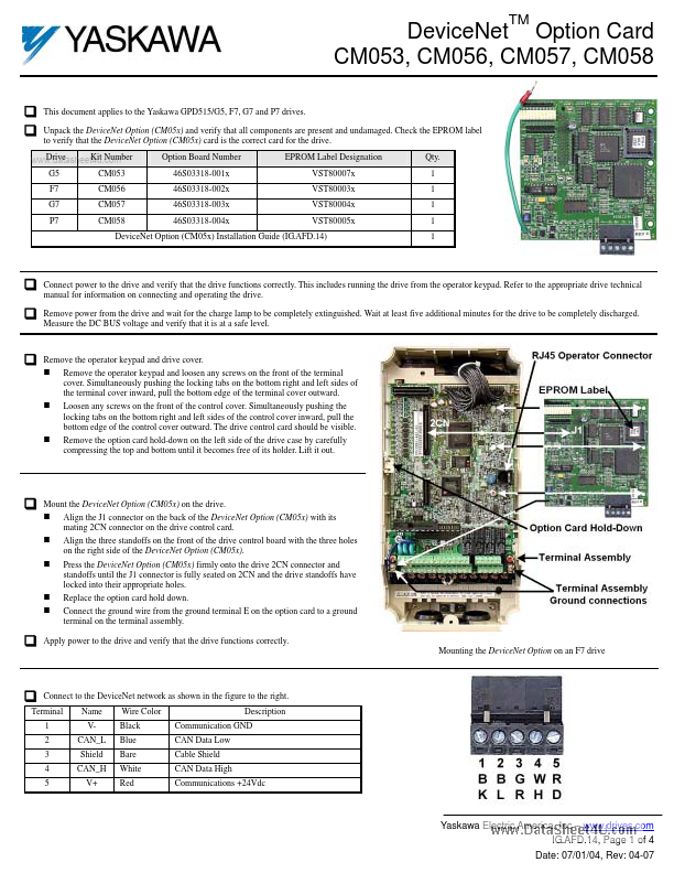
! Set the DeviceNet Option (CM05x) Baud Rate
Set the Baud Rate for the DeviceNet Option (CM05x) to the network baud rate by setting DIP switches 1 an 2 as shown in the figure to the right. The baud rate must match
the baud rate of the DeviceNet master (PC/PLC/Scanner) in order for the connection to function properly.
! Set the DeviceNet Option (CM05x) MAC ID
Set the MAC ID of DeviceNet Option (CM05x) by setting DIP switches 3 through 8 as shown in the table below. Each device on the network must have a unique MAC ID,
typically between 3 and 62. Addresses 0 and 1 are usually reserved for DeviceNet masters, address 2 for diagnostic/monitoring equipment and address 63 for vendor specific
functions in some systems. Check the network schematic to verify the MAC ID setting.
MAC ID
wSwww.0d0at0a1sh0e2e0t34u0.4co0m5 06 07 08 09 10 11 12 13 14 15 16 17 18 19 20 21 22 23 24 25 26 27 28 29 30 31
3 00000000000000000000000000000000
4 00000000000000001111111111111111
5 00000000111111110000000011111111
6 00001111000011110000111100001111
7 00110011001100110011001100110011
8 01010101010101010101010101010101
MAC ID
Sw 32 33 34 35 36 37 38 39 40 41 42 43 44 45 46 47 48 49 50 51 52 53 54 55 56 57 58 59 60 61 62 63
3 11111111111111111111111111111111
4 00000000000000001111111111111111
5 00000000111111110000000011111111
6 00001111000011110000111100001111
7 00110011001100110011001100110011
8 01010101010101010101010101010101
Sw Baud Rate
125kbps 250kbps 500kbps
10 0 1
20 1 0
N/A
1
1
Sw State
Function
9 0 Always Set to 0
1 Reserved
Master Idle Operation
Sw State
Function
10 0 EF0 Disabled
1 EF0 Enabled
A DeviceNet master is placed in “idle”
mode if it remains connected but stops
communicating. Sw 10 setting determines
the drive response to a master in “idle”
mode.
! Verify LED Status
Refer to the table on the following page for a complete listing of LED states.
LED Color
MS Green
MS Red
MS Green
NS Green
NS Red
LED Power-Up Sequence
Condition
On for 0.25 sec
On for 0.25 sec
On for 0.25 sec
On for 0.25 sec
On for 0.25 sec
LED normal operation Status
LED Condition
MS Green
NS Flash Green (No Communication)
Green (Communicating)
! Remove power from the drive and wait for the charge lamp to be completely
extinguished. Wait at least five additional minutes for the drive to be completely
discharged. Measure the DC BUS voltage and verify that it is at a safe level.
! Reinstall all drive covers and the operator keypad. Apply power to the drive.
! Set parameters b1-01 and b1-02 to their appropriate values. Refer to the table to
the right for available b1-01 and b1-02 values.
Param
Function
b1-01
Reference
Selection
Operation
b1-02 Method
Selection
Data +/- Limits - Description
0 Digital Operator
1 Terminals
2 Serial Communication
3 Option PCB (DeviceNet Option)
4 Pulse Input (F7 and G7 Only)
0 Digital Operator
1 Terminals
2 Serial Communication
3 Option PCB (DeviceNet Option)
Dflt
1
1
Yaskawa Electric America, Inc – www.drives.com
IG.AFD.14, Page 2 of 4
Date: 07/01/04, Rev: 04-07