The following content is an automatically extracted verbatim text
from the original manufacturer datasheet and is provided for reference purposes only.
View original datasheet text
www.vishay.com
CW
Vishay Dale
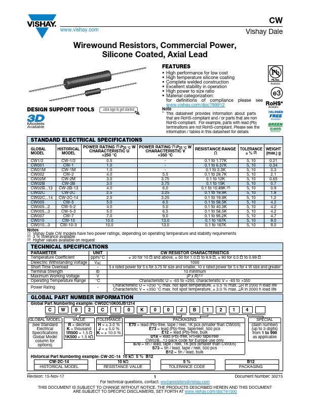
Wirewound Resistors, Commercial Power, Silicone Coated, Axial Lead
DESIGN SUPPORT TOOLS click logo to get started
Models
Available
FEATURES
• High performance for low cost • High temperature silicone coating • Complete welded construction • Excellent stability in operation • High power to size ratio • Material categorization:
for definitions of compliance please see www.vishay.com/doc?99912
Note
* This datasheet provides information about parts
that are RoHS-compliant and / or parts that are non
RoHS-compliant. For example, parts with lead (Pb)
terminations are not RoHS-compliant.
 CW001 Datasheet