MRF10005
MRF10005 is The RF Line Microwave Power Transistor manufactured by Tyco Electronics.
SEMICONDUCTOR TECHNICAL DATA
Order this document by MRF10005/D
The RF Line
Microwave Power Transistor
. . . designed for CW and long pulsed mon base amplifier applications, such as JTIDS and Mode S, in the 0.96 to 1.215 GHz frequency range at high overall duty cycles.
- Guaranteed Performance @ 1.215 GHz, 28 Vdc Output Power = 5.0 Watts CW Minimum Gain = 8.5 d B, 10.3 d B (Typ)
- RF Performance Curves given for 28 Vdc and 36 Vdc Operation
- 100% Tested for Load Mismatch at All Phase Angles with 10:1 VSWR
- Hermetically Sealed Industry Standard Package
- Silicon Nitride Passivated
- Gold Metallized, Emitter Ballasted for Long Life and Resistance to Metal Migration
- Internal Input Matching for Broadband Operation
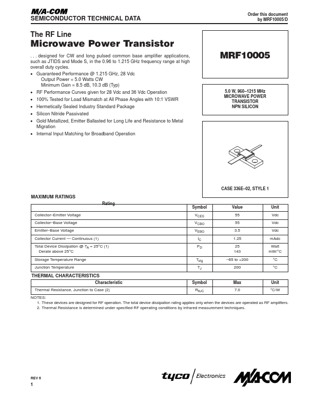
5.0 W, 960- 1215 MHz MICROWAVE POWER TRANSISTOR NPN SILICON
CASE 336E- 02, STYLE 1
MAXIMUM RATINGS
Rating Collector- Emitter Voltage Collector- Base Voltage Emitter- Base Voltage Collector Current
- Continuous (1) Total Device Dissipation @ TA = 25°C (1) Derate above 25°C Storage Temperature Range Junction Temperature Symbol VCES VCBO VEBO IC PD Tstg TJ Value 55 55 3.5 1.25 25 143
- 65 to +200 200 Unit Vdc Vdc Vdc m Adc Watt m W/°C °C °C
THERMAL CHARACTERISTICS
Characteristic Thermal Resistance, Junction to Case (2) Symbol RθJC Max 7.0 Unit °C/W
NOTES: 1. These devices are designed for RF operation. The total device dissipation rating applies only when the devices are operated as RF amplifiers. 2. Thermal Resistance is determined under specified RF operating conditions by infrared measurement techniques.
REV 6
ELECTRICAL CHARACTERISTICS (TC = 25°C unless otherwise noted.)
Characteristic Symbol Min Typ Max Unit
OFF CHARACTERISTICS
Collector- Emitter Breakdown Voltage (IC = 25 m Adc, VBE = 0) Collector- Base Breakdown Voltage (IC = 25 m Adc, IE = 0) Emitter- Base Breakdown Voltage (IE = 0.5 m Adc, IC = 0) Collector Cutoff Current (VCB = 28 Vdc, IE = 0) V(BR)CES V(BR)CBO V(BR)EBO ICBO 55 55 3.5
- -
- -
- -
- - 1.0 Vdc Vdc Vdc m Adc
ON CHARACTERISTICS...