Datasheet Details
| Part number | TC74HC595AFN |
|---|---|
| Manufacturer | Toshiba |
| File Size | 273.08 KB |
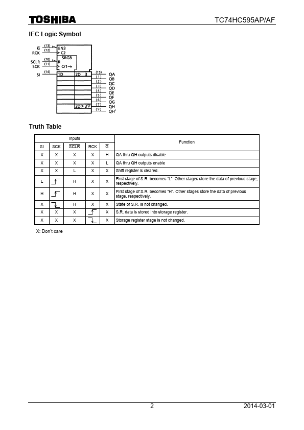
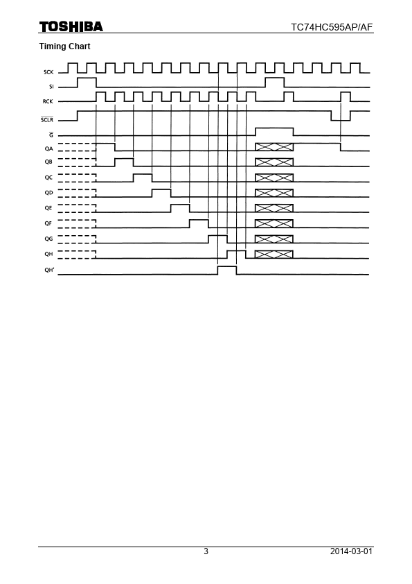
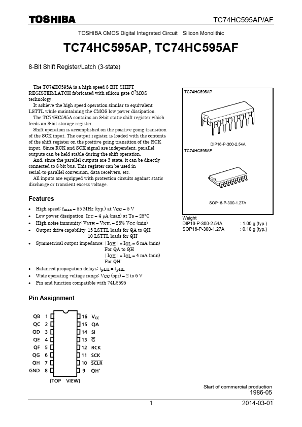
| Description | CMOS Digital Integrated Circuit Silicon Monolithic 8-Bit Shift Register/Latch |
| Datasheet |
 TC74HC595AFN Datasheet TC74HC595AFN Datasheet
|
|
|
Download the TC74HC595AFN datasheet PDF. This datasheet also covers the TC74HC595AF variant, as both devices belong to the same cmos digital integrated circuit silicon monolithic 8-bit shift register/latch family and are provided as variant models within a single manufacturer datasheet.
| Part number | TC74HC595AFN |
|---|---|
| Manufacturer | Toshiba |
| File Size | 273.08 KB |
| Description | CMOS Digital Integrated Circuit Silicon Monolithic 8-Bit Shift Register/Latch |
| Datasheet |
TC74HC595AFN Datasheet
|
|
|
|
| Part Number | Description | Manufacturer |
|---|---|---|
| TC74HC540AF | OCTAL BUS BUFFER | Toshiba |
| TC74HC540AP | OCTAL BUS BUFFER | Toshiba |
| TC74HC541AF | OCTAL BUS BUFFER | Toshiba |
| TC74HC541AP | OCTAL BUS BUFFER | Toshiba |
| TC74HC107AF | Dual J-K Flip-Flop | Toshiba |
| Part Number | Description |
|---|---|
| TC74HC595AF | 8-Bit Shift Register/Latch |
| TC74HC595AP | 8-Bit Shift Register/Latch |
| TC74HC590AF | 8-Bit Binary Counter/Register |
| TC74HC590AP | 8-Bit Binary Counter/Register |
| TC74HC592AF | 8-Bit Binary Counter |
The following content is an automatically extracted verbatim text from the original manufacturer datasheet and is provided for reference purposes only.