Datasheet Details
| Part number | TC7WH123FK |
|---|---|
| Manufacturer | Toshiba |
| File Size | 400.15 KB |
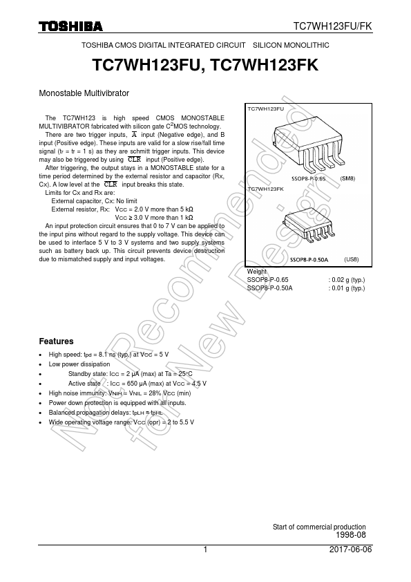
| Description | Monostable Multivibrator |
| Datasheet |
 TC7WH123FK Datasheet TC7WH123FK Datasheet
|
|
|
Download the TC7WH123FK datasheet PDF. This datasheet also covers the TC7WH123FU variant, as both devices belong to the same monostable multivibrator family and are provided as variant models within a single manufacturer datasheet.
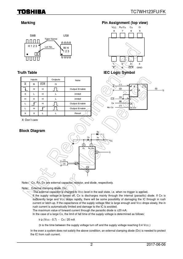
(1) Standby state The external capacitor (CX) is fully charged to VCC in the stand-by state.
the QP and QN transistors which are connected to the RX/CX node are in the off state.
| Part number | TC7WH123FK |
|---|---|
| Manufacturer | Toshiba |
| File Size | 400.15 KB |
| Description | Monostable Multivibrator |
| Datasheet |
TC7WH123FK Datasheet
|
|
|
|
| Part Number | Description | Manufacturer |
|---|---|---|
| TC7WBD125AFK | Dual Bus Switch | Toshiba Semiconductor |
| TC7WBD125FK | Dual Bus Switch | Toshiba Semiconductor |
| TC7WBD126AFK | Dual Bus Switch | Toshiba Semiconductor |
| TC7WBD126FK | Dual Bus Switch | Toshiba Semiconductor |
| TC7WP3125FC | Low Voltage/Low Power 2-Bit Dual Supply Bus Buffer | Toshiba Semiconductor |
| Part Number | Description |
|---|---|
| TC7WH123FU | Monostable Multivibrator |
| TC7WH125FK | Dual BUS Buffer |
| TC7WH125FU | Dual BUS Buffer |
| TC7WH126FK | Dual BUS Buffer |
| TC7WH126FU | Dual BUS Buffer |
The following content is an automatically extracted verbatim text from the original manufacturer datasheet and is provided for reference purposes only.