C4117
TOSHIBA Transistor Silicon NPN Epitaxial Type (PCT process)
2SC4117
Audio Frequency General Purpose Amplifier Applications
2SC4117
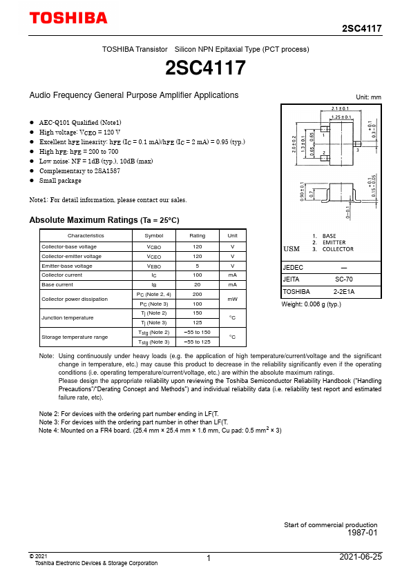
Unit: mm
- AEC-Q101 Qualified (Note1)
- High voltage: VCEO = 120 V
- Excellent h FE linearity: h FE (IC = 0.1 m A)/h FE (IC = 2 m A) = 0.95 (typ.)
- High h FE: h FE = 200 to 700
- Low noise: NF = 1d B (typ.), 10d B (max)
- plementary to 2SA1587
- Small package
Note1: For detail information, please contact our sales.
Absolute Maximum Ratings (Ta = 25°C)
Characteristics Collector-base voltage Collector-emitter voltage Emitter-base voltage Collector current Base current Collector power dissipation
Junction temperature
Storage temperature range
Symbol
Rating
Unit
VCBO
VCEO
VEBO
100 m A
20 m A
PC (Note 2, 4)
200 m W
PC (Note 3)
Tj (Note 2)
°C
Tj (Note 3)
Tstg (Note...