Datasheet4U Logo Datasheet4U.com

XC8111 - Load switch

Download the XC8111 datasheet PDF. This datasheet also covers the XC8110 variant, as both devices belong to the same load switch family and are provided as variant models within a single manufacturer datasheet.
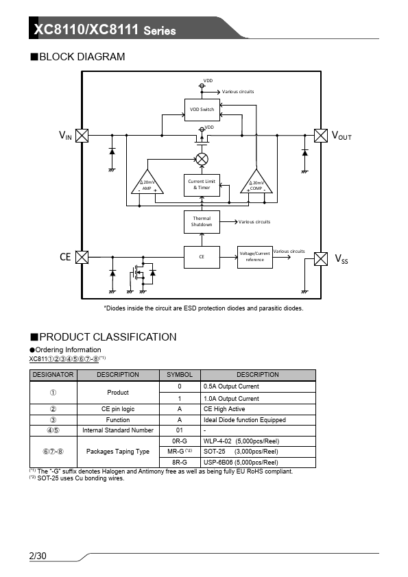
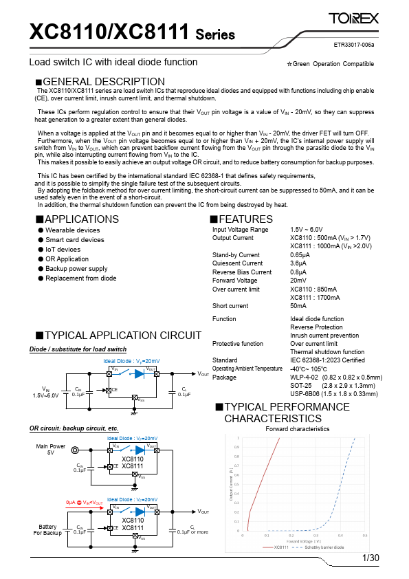
Description

(CE), over current limit, inrush current limit, and thermal shutdown.

Features

  • ut Voltage Range Output Current Stand-by Current Quiescent Current Reverse Bias Current Forward Voltage Over current limit Short current 1.5V ~ 6.0V XC8110 : 500mA (VIN > 1.7V) XC8111 : 1000mA (VIN >2.0V) 0.65μA 3.6μA 0.8μA 20mV XC8110 : 850mA XC8111 : 1700mA 50mA Function Ideal diode function Reverse Protection.

📥 Download Datasheet

Note: The manufacturer provides a single datasheet file (XC8110-Torex.pdf) that lists specifications for multiple related part numbers.

Full PDF Text Transcription (Reference)

The following content is an automatically extracted verbatim text from the original manufacturer datasheet and is provided for reference purposes only.

View original datasheet text
XC8110/XC8111 Series ETR33017-006a Load switch IC with ideal diode function ☆Green Operation Compatible ■GENERAL DESCRIPTION The XC8110/XC8111 series are load switch ICs that reproduce ideal diodes and equipped with functions including chip enable (CE), over current limit, inrush current limit, and thermal shutdown. These ICs perform regulation control to ensure that their VOUT pin voltage is a value of VIN - 20mV, so they can suppress heat generation to a greater extent than general diodes. When a voltage is applied at the VOUT pin and it becomes equal to or higher than VIN - 20mV, the driver FET will turn OFF.
Published: |