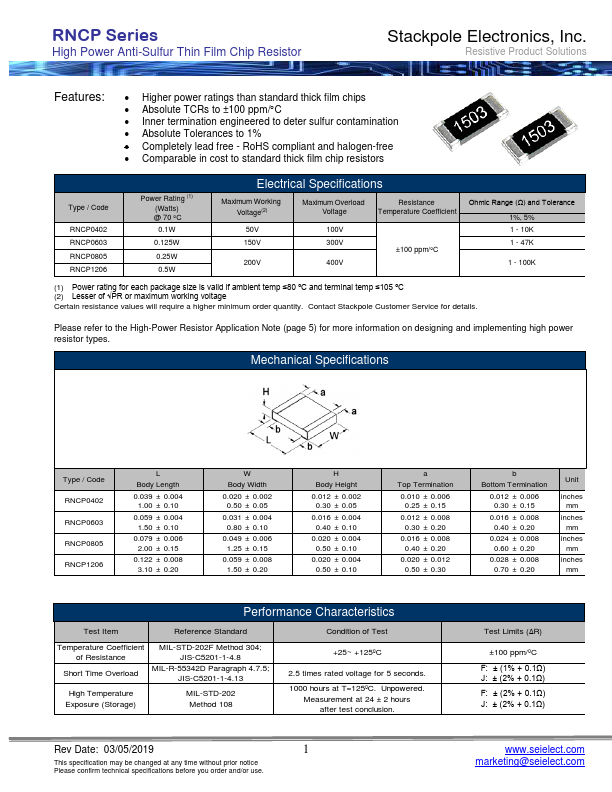
RNCP1206
RNCP1206 is High Power Anti-Sulfur Thin Film Chip Resistor manufactured by Stackpole.
- Part of the RNCP0402 comparator family.
- Part of the RNCP0402 comparator family.
Features
:
- Higher power ratings than standard thick film chips
- Absolute TCRs to ±100 ppm/C
- Inner termination engineered to deter sulfur contamination
- Absolute Tolerances to 1%
- pletely lead free
- Ro HS pliant and halogen-free
- parable in cost to standard thick film chip resistors
Type / Code
RNCP0402 RNCP0603 RNCP0805 RNCP1206
Power Rating (1) (Watts) @ 70 ºC 0.1W
0.125W
0.25W
0.5W
Electrical Specifications
Maximum Working Voltage(2)
Maximum Overload
Resistance
Voltage
Temperature Coefficient
50V 150V
200V
100V 300V
400V
±100 ppm/ºC
Ohmic Range (Ω) and Tolerance 1%, 5% 1
- 10K 1
- 47K
- 100K
(1) Power rating for each package size is valid if ambient temp ≤80 ºC and terminal temp ≤105 ºC (2) Lesser of √PR or maximum working voltage
Certain resistance values will require a higher minimum order quantity....