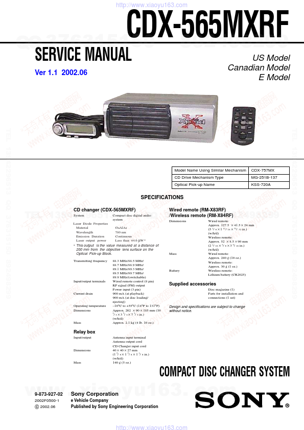
CDX-565MXRF
http://www.xiaoyu163.com
SERVICING NOTES
NOTES ON HANDLING THE OPTICAL PICK-
QQ 376315150 892498299UP BLOCK OR BASE UNIT
JIG ON REPAIRING
When repairing this set, connect the jig (cord) for RF output ex-
tract (Part No. J-2502-058-1) and power supply (Part No. J-2502-
The laser diode in the optical pick-up block may suffer electro-
058-2) as the figure shown below.
static breakdown because of the potential difference generated by
the charged electrostatic load, etc. on clothing and the human body.
During repair, pay attention to electrostatic breakdown and also
use the procedure in the printed matter which is included in the
repair parts.
The flexible board is easily damaged and should be handled with
RF output cord
power supply cord
care.
(J-2502-058-1)
(J-2502-058-2)
NOTES ON LASER DIODE EMISSION CHECK
The laser beam on this model is concentrated so as to be focused
on the disc reflective surface by the objective lens in the optical
pick-up block. Therefore, when checking the laser diode emis-
sion, observe from more than 30 cm away from the objective lens.
US/Canadian model:
If the optical pick-up block is defective, please replace the whole
optical pick-up block.
Never turn the semi-fixed resistor located at the side of optical
pick-up block.
compact disc changer
OPTICAL
PICK-UP
BLOCK
TEL 13942296513
SEMI-FIXED
RESISTOR
wired remote commander
DISC MAGAZINE GETTING OUT PROCEDURE
QQ 376315150 892498299ON THE POWER SUPPLY IS OFF
Remove the CASE (LOWER. T) beforehand
1) Press the lever (ML.S) assy in the direction of arrow A.
2) Removal the magazine assy.
Note: Take out the magazine only when the tray is completely within the
magazine. If the disk or tray is sticking out, turn on the power and
eject the magazine.
CAUTION
Use of controls or adjustments or performance of procedures
other than those specified herein may result in hazardous ra-
diation exposure.
Lever (ML.S)
Flexible Circuit Board Repairing
• Keep the temperature of the soldering iron around 270 ˚C dur-
ing repairing.
• Do not touch the soldering iron on the same conductor of the
circuit board (within 3 times).
• Be careful not to apply force on the conductor when soldering
or unsoldering.
Magazine assy
A
Notes on chip component replacement
• Never reuse a disconnected chip component.
• Notice that the minus side of a tantalum capacitor may be dam-
aged by heat.
ATTENTION AU COMPOSANT AYANT RAPPORT
À LA SÉCURITÉ!
SAFETY-RELATED COMPONENT WARNING!!
COMPONENTS IDENTIFIED BY MARK 0 OR DOTTED LINE
WITH MARK 0 ON THE SCHEMATIC DIAGRAMS AND IN
THE PARTS LIST ARE CRITICAL TO SAFE OPERATION.
www . xiaoy u163. comREPLACE THESE COMPONENTS WITH SONY PARTS
LES COMPOSANTS IDENTIFIÉS PAR UNE MARQUE 0
SUR LES DIAGRAMMES SCHÉMATIQUES ET LA LISTE
DES PIÈCES SONT CRITIQUES POUR LA SÉCURITÉ
DE FONCTIONNEMENT. NE REMPLACER CES COM-
POSANTS QUE PAR DES PIÈCES SONY DONT LES
WHOSE PART NUMBERS APPEAR AS SHOWN IN THIS
NUMÉROS SONT DONNÉS DANS CE MANUEL OU
MANUAL OR IN SUPPLEMENTS PUBLISHED BY SONY.
DANS LES SUPPLÉMENTS PUBLIÉS PAR SONY.
2
http://www.xiaoyu163.com