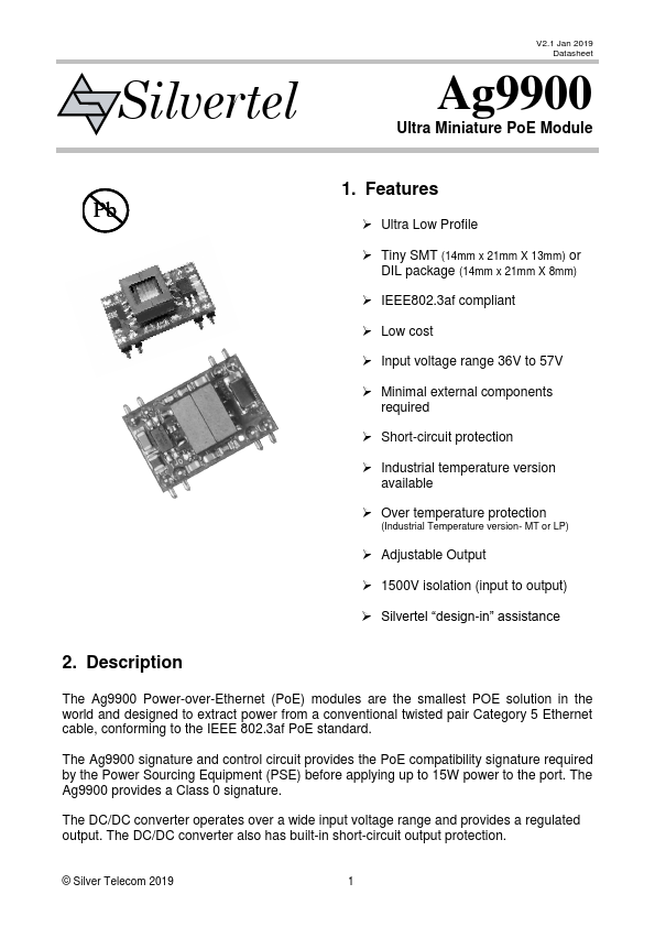
V2.1 Jan 2019
Data Sheet
Ag9900
Power-Over-Ethernet Module
Table of Contents
1. Features .......................................................................................................................1
2. Description....................................................................................................................1
Table of Contents .............................................................................................................2
Table of Figures ...............................................................................................................2
3. Pin Description .............................................................................................................5
3.1 Ag9900 ..................................................................................................................6
4. Functional Description ..................................................................................................7
4.1 Inputs.....................................................................................................................7
4.2 PD Signature .........................................................................................................7
4.3 Isolation .................................................................................................................7
4.4 Power Classification ..............................................................................................8
4.5 DC/DC Converter ..................................................................................................8
4.6 Output Adjustment.................................................................................................8
4.7 Typical Connections ..............................................................................................9
4.8 Additional Output Filtering ...................................................................................10
4.9 Start-up Power.....................................................................................................10
5. Typical Application......................................................................................................11
6. Operating Temperature Range ...................................................................................11
7. Layout Consideration..................................................................................................16
8. Protection ...................................................................................................................17
8.1 Input Protection ...................................................................................................17
8.2 Thermal Protection ..............................................................................................18
9. EMC............................................................................................................................18
10. Electrical Characteristics.........................................................................................19
10.1 Absolute Maximum Ratings1................................................................................19
10.2 Recommended Operating Conditions..................................................................19
10.3 DC Electrical Characteristics ...............................................................................19
11. Package ..................................................................................................................21
11.1 Ag9900M/MT .......................................................................................................21
11.2 Ag9900LP............................................................................................................22
Table of Figures
Figure 1: Block Diagram ......................................................................................................5
Figure 2: Ag9900 Package Format ......................................................................................5
Figure 3: Typical System Diagram .......................................................................................7
Figure 4: Output Adjustment ................................................................................................8
Figure 5: Typical Connection Diagram.................................................................................9
Figure 6: Output Filtering ...................................................................................................10
Figure 7: Typical Application..............................................................................................11
Figure 8: Ag9924M Operating Profile ................................................................................12
Figure 9: Ag9912M Operating Profile ................................................................................12
Figure 10: Ag9905M Operating Profile ..............................................................................13
Figure 11: Ag9903M Operating Profile ..............................................................................13
Figure 12: Ag9912LP Operating Profile .............................................................................13
Figure 13: Ag9905LP Operating Profile .............................................................................14
Figure 14: Ag9903LP Operating Profile .............................................................................14
© Silver Telecom 2019
2