Ag6100
Features
Pb
- pliant with IEEE802.3at Type 1(af) & Type 2
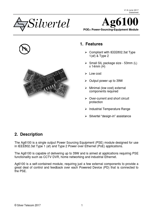
- Small SIL package size
- 53mm (L) x 14mm (H)
- Low cost
- Output power up to 39W
- Minimal (low cost) external ponents required
- Over-current and short circuit protection
- Industrial Temperature Range
- Silvertel “design-in” assistance
2. Description
The Ag6100 is a single output Power Sourcing Equipment (PSE) module designed for use in IEEE802.3at Type 1 (af) and Type 2 Power over Ethernet (Po E) applications.
The Ag6100 is capable of delivering up to 39W and is aimed at applications requiring PSE functionality such as CCTV DVR, home networking and industrial Ethernet.
Ag6100 is a self-contained module, requiring just a few external ponents to provide a great deal of control and feedback over each Powered Device (PD) that is connected to the PSE.
© Silver Tele 2017
V1.6 June 2017 Data...