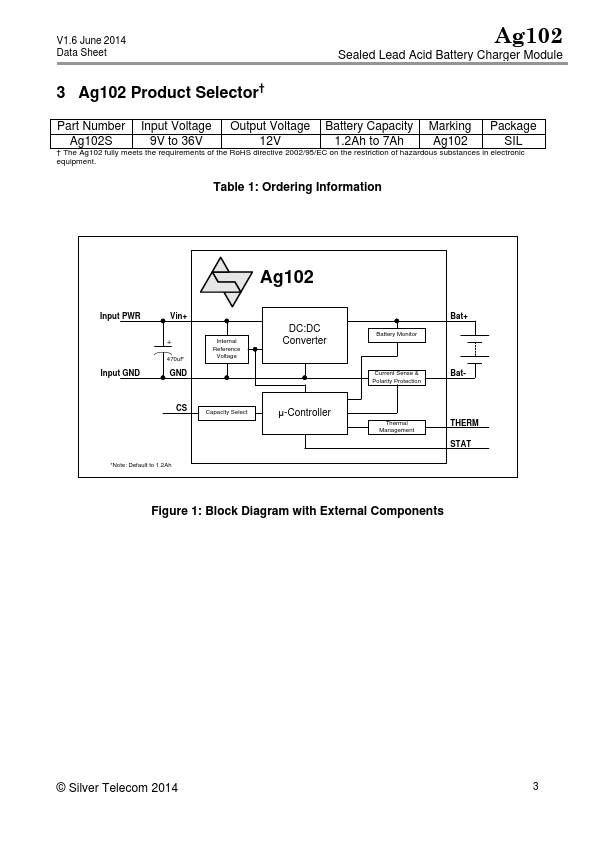
V1.6 June 2014
Data Sheet
Table of Contents
Ag102
Sealed Lead Acid Battery Charger Module
1 Features .......................................................................................................................1
2 Description....................................................................................................................1
2.1 Table of Figures.....................................................................................................2
3 Ag102 Product Selector† ..............................................................................................3
4 Pin Description .............................................................................................................4
5 Functional Description ..................................................................................................5
5.1 Operation...............................................................................................................5
5.2 Input ......................................................................................................................6
5.3 Capacity Select......................................................................................................7
5.4 Thermal Compensation .........................................................................................8
5.5 Status Output.........................................................................................................9
5.5.1 Mode 0 – Normal Operation .........................................................................10
5.5.2 Mode 1 – Battery Capacity Warning.............................................................10
5.5.3 Mode 2 – Defective or Disconnected battery................................................11
5.5.4 Mode 3 – Over Temperature ........................................................................11
5.5.5 Mode 4 – Over Current.................................................................................11
6 Typical Application......................................................................................................12
7 Operating Temperature Range ...................................................................................13
8 Protection ...................................................................................................................13
8.1 Battery Reversal Protection .................................................................................13
8.2 Over Current & Short Circuit Protection...............................................................13
8.3 Over Temperature Protection ..............................................................................13
8.4 Low Battery Terminal Voltage Protection ............................................................13
9 Electrical Characteristics ............................................................................................14
9.1 Absolute Maximum Ratings*................................................................................14
9.2 Recommended Operating Conditions..................................................................14
9.3 DC Electrical Characteristics*..............................................................................14
10 Package ..................................................................................................................15
2.1 Table of Figures
Figure 1: Block Diagram with External Components............................................................3
Figure 2: Ag102 SIL Package Format..................................................................................4
Figure 3: Basic Ag102 Charge Profile..................................................................................5
Figure 4: Input Connections – DC or AC Input.....................................................................6
Figure 5: Capacity Select.....................................................................................................7
Figure 6: Output Adjustment ................................................................................................8
Figure 7: STAT Output Configurations.................................................................................9
Figure 8: STAT Output Timing ...........................................................................................10
Figure 9: Typical Application..............................................................................................12
© Silver Telecom 2014
2