Datasheet4U Logo Datasheet4U.com

C8051F330 - (C8051F330 - C8051F335) Mixed Signal ISP Flash MCU

Description

83 9.3.

Interrupt Handler 85 9.3.1.

MCU Interrupt Sources and Vectors 86 9.3.2.

Features

  • 23 1.2. On-Chip Memory 24 1.3. On-Chip Debug Circuitry 25 1.4. Programmable Digital I/O and Crossbar 26 1.5. Serial Ports 26 1.6. Programmable Counter Array 27 1.7. 10-Bit Analog to Digital Converter 28 1.8. Comparators 29 1.9. 10-bit Current Output DAC 30 2. Absolute Maximum Ratings 31 3. Global Electrical Characteristics 32 4. Pinout and Package Definitions 35 5. 10-Bit ADC (ADC0, C8051F330/2/4 only) 41 5.1. Analog Multiplexer 41 5.2. Temperature Sensor 42 5.3. Modes of Operation 43.

📥 Download Datasheet

Full PDF Text Transcription (Reference)

The following content is an automatically extracted verbatim text from the original manufacturer datasheet and is provided for reference purposes only.

View original datasheet text
Analog Peripherals - 
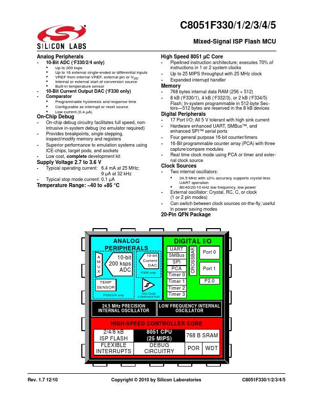
10-Bit ADC (‘F330/2/4 only) • Up to 200 ksps • Up to 16 external single-ended or differential inputs • VREF from internal VREF, external pin or VDD • Internal or external start of conversion source • Built-in temperature sensor - 10-Bit Current Output DAC (‘F330 only) - Comparator • Programmable hysteresis and response time • Configurable as interrupt or reset source • Low current (0.4 µA) On-Chip Debug - On-chip debug circuitry facilitates full speed, nonintrusive in-system debug (no emulator required) - Provides breakpoints, single stepping, inspect/modify memory and registers - Superior performance to emulation systems using ICE-chips, target pods, and sockets - Low cost, complete development kit Supply Voltage 2.7 to 3.6 V - Typical operating current: 6.
Published: |