M74HC590 Overview
Key Specifications
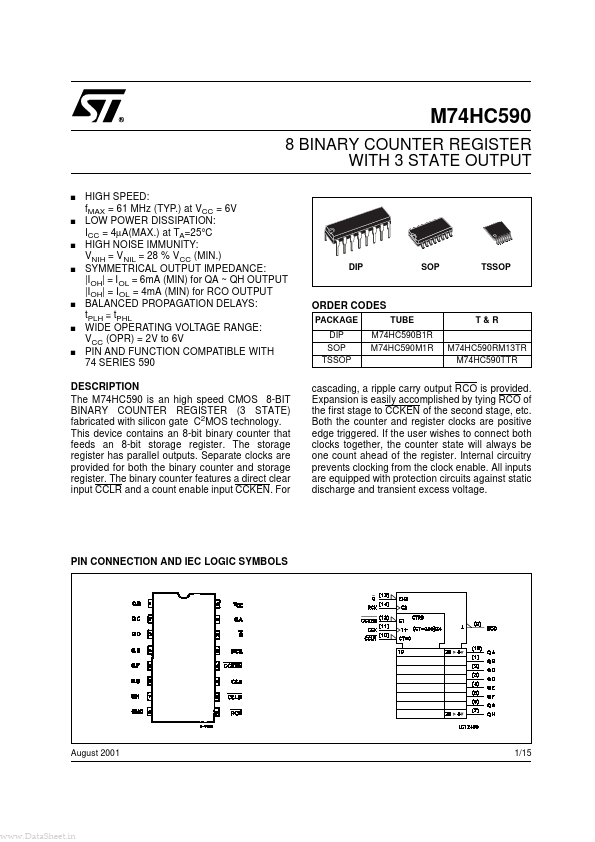
Package: DIP
Mount Type: Through Hole
Pins: 16
Operating Voltage: 4.5 V
Description
The M74HC590 is an high speed CMOS 8-BIT BINARY COUNTER REGISTER (3 STATE) fabricated with silicon gate C2MOS technology. This device contains an 8-bit binary counter that feeds an 8-bit storage register.
Key Features
- a direct clear input CCLR and a count enable input CCKEN
- For cascading, a ripple carry output RCO is provided
- Expansion is easily accomplished by tying RCO of the first stage to CCKEN of the second stage, etc
- Both the counter and register clocks are positive edge triggered
- If the user wishes to connect both clocks together, the counter state will always be one count ahead of the register