27C1001 Overview
Key Specifications
Package: CDIP
Mount Type: Through Hole
Pins: 32
Operating Voltage: 5 V
Description
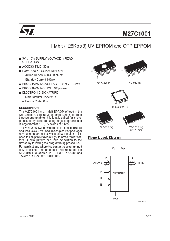
The M27C1001 is a 1 Mbit EPROM offered in the two ranges UV (ultra violet erase) and OTP (one time programmable). It is ideally suited for microprocessor systems requiring large programs and is organized as 131,072 words of 8 bits.