Part number:
SM4934
Manufacturer:
SEP ELECTRONIC
File Size:
32.24 KB
Description:
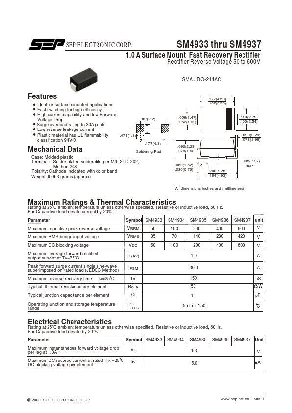
1.0a surface mount fast recovery rectifier.
SM4934 Features
* Ideal for surface mounted applications Fast switching for high efficiency High current capability and low Forward Voltage Drop Surge overload rating to 30A peak Low reverse leakage current .087(2.2) Plastic material has UL flammability classification 94V-0 Mechanical Data .071(1.8) .177(4.8) Sol
Datasheet Details
SM4934
SEP ELECTRONIC
32.24 KB
1.0a surface mount fast recovery rectifier.
📁 Related Datasheet
SM4933 1A SURACE MOUNT FAST RECOVERY RECTIFIERS (Frontier Electronics)
SM4933 SURFACE MOUNT FAST RECOVERY RECTIFIER (Dc Components)
SM4933 FAST RECOVERY SILICON RECTIFIERS (SEMTECH)
SM4933 FAST RECOVERY RECTIFIER (MIC)
SM4933 1 Amp Fast Recovery Rectifier (MCC)
SM4933 1.0A Surface Mount Fast Recovery Rectifier (SEP ELECTRONIC)
SM4933 FAST RECOVERY SILICON RECTIFIER (Rectron Semiconductor)
SM4933 1.0 AMP SURFACE MOUNT FAST RECOVERY RECTIFIERS (Formosa MS)
SM4934 Distributor