CR05BS-8
CR05BS-8 is Thyristor manufactured by Renesas.
..
Thyristor
Low Power Use
Features
- IT (AV) : 0.1 A
- VDRM : 400 V
- IGT : 100 µA
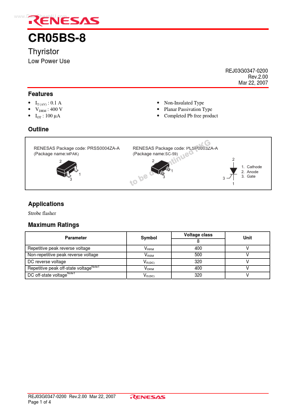
Outline
REJ03G0347-0200 Rev.2.00
Mar 22, 2007
- Non-Insulated Type
- Planar Passivation Type
- pleted Pb free product
RENESAS Package code: PRSS0004ZA-A (Package name:MPAK)
1 3
RENESAS Package code: PLSP0003ZA-A
(Package name:SC-59)
1 3
1. Cathode
2. Anode
3. Gate
Applications
Strobe flasher
Maximum Ratings
Parameter
Repetitive peak reverse voltage Non-repetitive peak reverse voltage DC reverse voltage Repetitive peak off-state voltageNote1 DC off-state voltageNote1
Symbol
VRRM VRSM VR(DC) VDRM VD(DC)
Voltage class 8
400 500 320 400...