CR05AS-8
Key Features
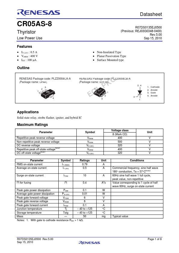
- IT (AV) : 0.5 A
- VDRM : 400 V
- IGT : 100 A Outline Preliminary Datasheet
| Part Number | Manufacturer | Description |
|---|---|---|
| CR05AS | Kexin Semiconductor | Silicon Controlled Rectifiers |
| CR05AS | Mitsubishi Electric | Thyristor |
| CR05AM-16A | Renesas | Thyristor |