The following content is an automatically extracted verbatim text
from the original manufacturer datasheet and is provided for reference purposes only.
View original datasheet text
R1204x Series
Step-up DC/DC Converter with Shutdown Function
No. EA-284-180511
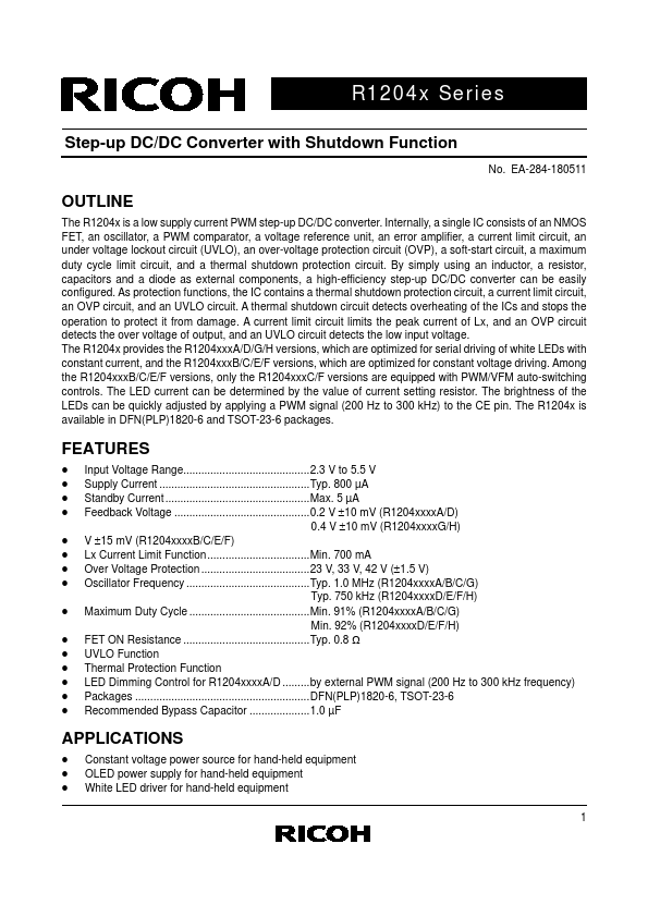
OUTLINE
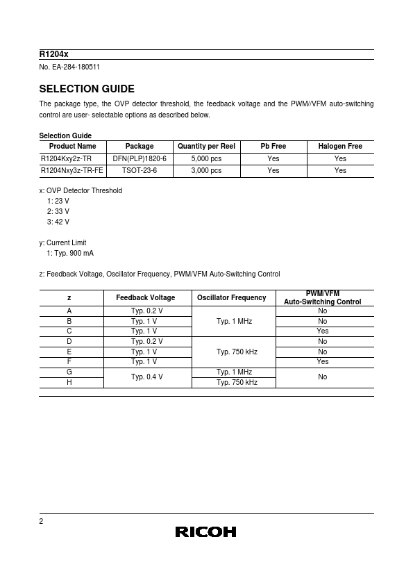
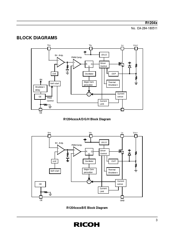
The R1204x is a low supply current PWM step-up DC/DC converter. Internally, a single IC consists of an NMOS FET, an oscillator, a PWM comparator, a voltage reference unit, an error amplifier, a current limit circuit, an under voltage lockout circuit (UVLO), an over-voltage protection circuit (OVP), a soft-start circuit, a maximum duty cycle limit circuit, and a thermal shutdown protection circuit. By simply using an inductor, a resistor, capacitors and a diode as external components, a high-efficiency step-up DC/DC converter can be easily configured. As protection functions, the IC contains a thermal shutdown protection circuit, a current limit circuit, an OVP circuit, and an UVLO circuit.
 R1204K212C-TR Datasheet