Part number:
1N1195A
Manufacturer:
RCA
File Size:
254.47 KB
Description:
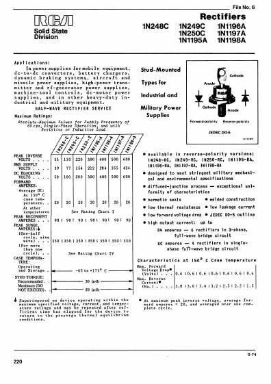
Rectifiers.
Datasheet Details
1N1195A
RCA
254.47 KB
Rectifiers.
📁 Related Datasheet
1N1195 Medium current silicon rectifiers (Motorola)
1N1195A Medium current silicon rectifiers (Motorola)
1N119 Gold Bonded Diode (BKC)
1N1190 STANDARD RECOVERY RECTIFIERS (Digitron Semiconductors)
1N1190 Silicon-Power Rectifiers (Diotec Semiconductor)
1N1190 35/40/and 60 Amp Power Silicon Rectifier Diodes (International Rectifier)
1N1190 Silicon Standard Recovery Diode (GeneSiC)
1N1190 Silicon Standard Recovery Diode (America Semiconductor)
TAGS
1N1195A Distributor