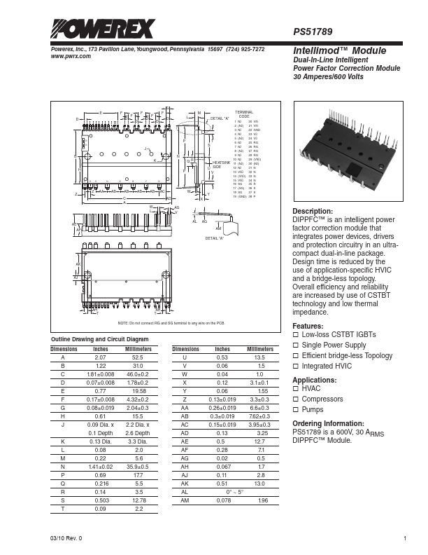
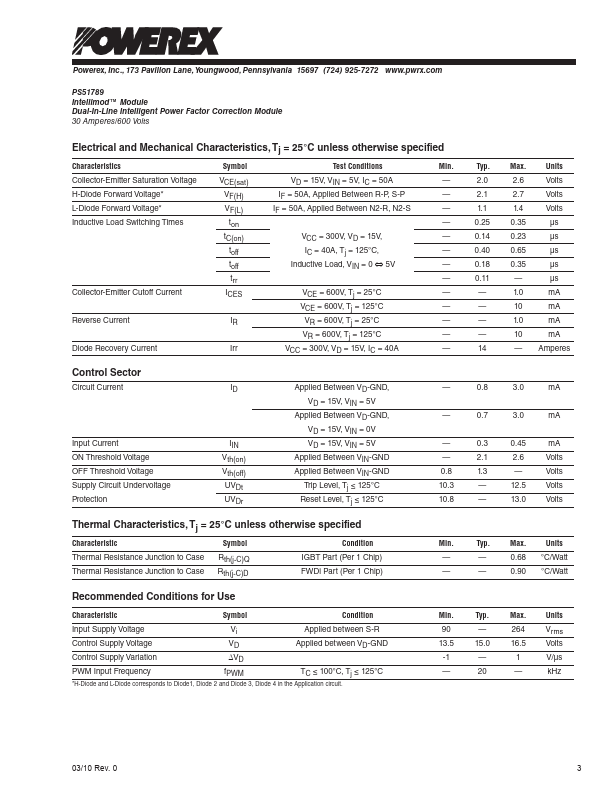
Powerex, Inc., 173 Pavilion Lane, Youngwood, Pennsylvania 15697 (724) 925-7272 www.pwrx.com
PS51789
Intellimod™ Module
Dual-In-Line Intelligent Power Factor Correction Module
30 Amperes/600 Volts
Absolute Maximum Ratings, Tj = 25°C unless otherwise specified
Characteristics
Symbol
Input Supply Voltage (Between S-R Terminals)
Input Supply Voltage, Surge (Between S-R Terminals)
Output Voltage (Between P-N Terminals)
Output Voltage, Surge (Between P-N Terminals)
Collector-Emitter Voltage
Repetative Peak Reverse Voltage
Input Current, 100% Load (TC ≤ 100°C, Vi = 220Vrms, VO = 390V, fPWM = 20kHz)
Input Current, 125% Load (TC ≤ 100°C, Vi = 220Vrms, VO = 390V,
fPWM = 20kHz, Non-repetative, within 1 Minute)
I2t for Fusing (Value for 1 Cycle of Surge Current, tw = 8.3ms)
Vi
Vi(surge)
VO
VO(surge)
VCES
VRRM
Ii
Ii(125%)
I2t
Junction Temperature*
Module Case Operation Temperature
Storage Temperature
Mounting Torque, M3 Mounting Screws
Tj
TC
Tstg
—
Module Weight (Typical)
—
Isolation Voltage, AC 1 minute, 60Hz Sinusoidal, Connection Pins to Heatsink Plate
VISO
PS51789
264
500
450
500
600
600
30
37.5
270
-20 to 150
-20 to 100
-40 to 125
8.7
21
2500
Control Sector
Control Supply Voltage (Applied between VD-GND)
VD 20
Input Voltage (Applied between VIN-GND)
VIN 0 ~ VD+0.5
Fault Output Supply Voltage (Applied between FO-VNC)
VFO
-0.5 ~ VD+0.5
Fault Output Current (Sink Current at FO Terminal)
IFO 1
Current Sensing Input Voltage (Applied between CIN-VNC)
VSC
-0.5 ~ VD+0.5
*The maximum junction temperature rating of the power chips integrated within the DIPPFC is 150°C (@TC ≤ 100°C). However, to ensure safe operation of the DIPPFC,
the average junction temperature should be limited to Tj(avg) ≤ 125°C (@TC ≤ 100°C).
Units
Vrms
Volts
Volts
Volts
Volts
Volts
Arms
Arms
A2s
°C
°C
°C
in-lb
Grams
Vrms
Volts
Volts
Volts
mA
Volts
TC Measurement Point
CONTROL TERMINALS
4.6 mm
IGBT
25.4mm
POWER TERMINALS
TC POINT
2 03/10 Rev. 0