CM10MD1-24H Overview
Description
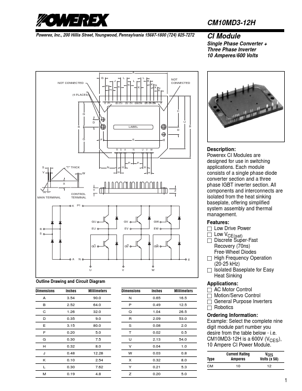
Powerex CI Modules are designed for use in switching applications. Each module consists of a single phase diode converter section and a three phase IGBT inverter section.
Key Features
- CM10MD3-12H is a 600V (VCES), 10 Ampere CI Power Module