PSMN015-100P Overview
Key Specifications
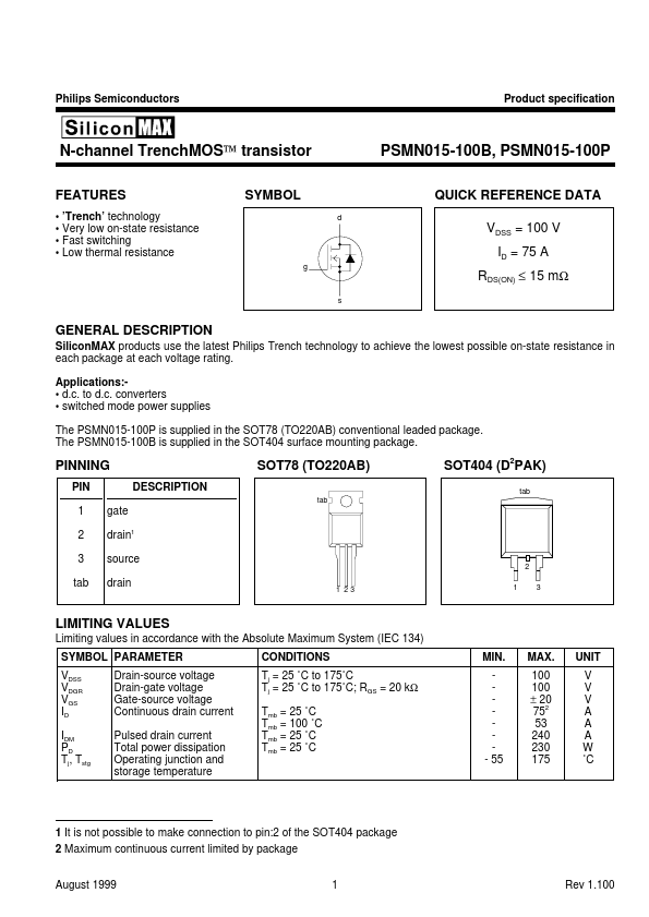
Pins: 3
Max Operating Temp: 175 °C
Min Operating Temp: -55 °C
Description
SiliconMAX products use the latest Philips Trench technology to achieve the lowest possible on-state resistance in each package at each voltage rating. converters - switched mode power supplies The PSMN015-100P is supplied in the SOT78 (TO220AB) conventional leaded package.
Key Features
- Very low on-state resistance
- Fast switching
- Low g PSMN015-100B, PSMN015-100P QUICK REFERENCE DATA d SYMBOL VDSS = 100 V ID = 75 A RDS(ON) ≤ 15 mΩ s