P8X32A-M44
P8X32A-M44 is 8-Cog Multiprocessor Microcontroller manufactured by Parallax.
- Part of the P8X32A comparator family.
- Part of the P8X32A comparator family.
OVERVIEW
1.1. Introduction The Propeller chip is designed to provide high-speed processing for embedded systems while maintaining low current consumption and a small physical footprint. In addition to being fast, the Propeller chip provides flexibility and power through its eight processors, called cogs, that can perform simultaneous tasks independently or cooperatively, all while maintaining a relatively simple architecture that is easy to learn and utilize. Two programming languages are available: Spin (a high-level object-based language) and Propeller Assembly. Both include custom mands to easily manage the Propeller chip’s unique features
.
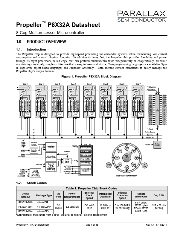
Figure 1: Propeller P8X32A Block Diagram
1.2. Stock Codes
Table 1: Propeller Chip Stock Codes
Device Stock #
Package Type
I/O Power Pins Requirements
External Clock Speed
Internal RC Oscillator
Internal Execution
Speed
P8X32A-D40 P8X32A-Q44 P8X32A-M44
40-pin DIP 44-pin LQFP 44-pin QFN
32 CMOS
3.3 volts DC
DC to 80 MHz
12 MHz or 20 k Hz-
- Approximate; may range from 8 MHz
- 20 MHz, or 13 k Hz
- 33 k Hz, respectively.
0 to 160 MIPS (20 MIPS/cog)
Global ROM/RAM
64 K bytes; 32768 bytes ROM / 32768 bytes RAM
Cog RAM
512 x 32 bits per cog
Parallax, Propeller, Spin, and the Parallax and Propeller logos are trademarks of Parallax, Inc. All other trademarks are the property of their respective holders.
Copyright © Parallax Inc.
Page 1 of 37
Rev 1.2 4/24/2009
Propeller™ P8X32A Datasheet
Table of Contents
1.0 Product Overview
1.1. Introduction 1 1.2. Stock Codes 1 1.3. Key Features
3 1.4. Programming Advantages 3 1.5. Applications...