Datasheet4U.com
🌙
UN6113
UN6118
UN6117
UN6111
UN6116
UN6119
UN6113 Datasheet | Panasonic
Part
UN6113
Description
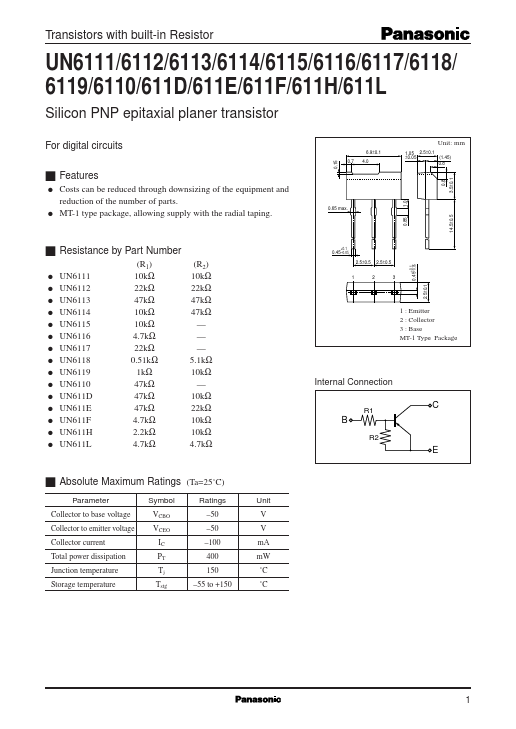
Silicon PNP epitaxial planer transistor
Category
Transistor
Manufacturer
Panasonic
Size
181.81 KB
UN6113 Datasheet (PDF) Download
Panasonic
UN6113
Overview
0 1 Transistors with built-in Resistor
Related Datasheets
KD333
— Tesla Elektronicke — Transistor
C828
— SEMTECH — NPN Silicon Transistor
2N2222
— SEMTECH — NPN Silicon Transistor
This website uses cookies or similar technologies, to enhance your browsing experience and provide personalized recommendations.
By continuing to use our website, you agree to our
Privacy Policy
Accept