2SD2598 Overview
Key Specifications
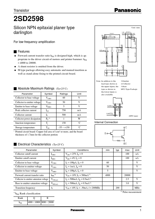
Package: SIP
Mount Type: Through Hole
Pins: 3
Key Features
- 1.0 1.0 0.2 Unit nA nA V V V VCE(sat) VBE(sat) fT V V
| Part | 2SD2598 |
|---|---|
| Description | Silicon NPN Transistor |
| Category | Transistor |
| Manufacturer | Panasonic |
| Size | 54.18 KB |
Package: SIP
Mount Type: Through Hole
Pins: 3
| Seller | Inventory | Price Breaks | Buy |
|---|---|---|---|
| Win Source | 5 | - | View Offer |
| Part Number | Manufacturer | Description |
|---|---|---|
| 2SD257 | Unknown Manufacturer | NPN Transistor |
| 2SD2599 | Toshiba | Silicon NPN Transistor |
| 2SD259 | Unknown Manufacturer | NPN Transistor |
| D2599 | Toshiba | 2SD2599 |
| 2SD2599 | SavantIC | SILICON POWER TRANSISTOR |