P4SMA15 Overview
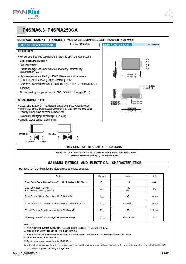
P4SMA6.8~P4SMA250CA SURFACE MOUNT TRANSIENT VOLTAGE SUPPRESSOR POWER 400 Watt BREAK DOWN VOLTAGE 6.8 to 250 Volt.
P4SMA15 Key Features
- For surface mounted
P4SMA15 datasheet by PanJit Semiconductor.
This datasheet includes multiple variants, all published together in a single manufacturer document.
| Part number | P4SMA15 |
|---|---|
| Datasheet | P4SMA15 P4SMA6.8 Datasheet (PDF) |
| File Size | 233.35 KB |
| Manufacturer | PanJit Semiconductor |
| Description | SURFACE MOUNT TRANSIENT VOLTAGE SUPPRESSOR |
|
|
P4SMA6.8~P4SMA250CA SURFACE MOUNT TRANSIENT VOLTAGE SUPPRESSOR POWER 400 Watt BREAK DOWN VOLTAGE 6.8 to 250 Volt.
| Brand Logo | Part Number | Description | Other Manufacturers |
|---|---|---|---|
| P4SMA15 | Surface Mount Transient Voltage Suppressor | FAGOR | |
| P4SMA15 | Surface Mount Transient Voltage Suppressor | Taiwan Semiconductor | |
| P4SMA15 | Transient Voltage Suppressor | Bruckewell | |
| P4SMA15 | TRANSIENT VOLTAGE SUPPRESSOR | GME | |
| E-DA SEMICONDUCTOR | P4SMA15 | TRANSIENT VOLTAGE SUPPRESSOR | E-DA SEMICONDUCTOR |
View all PanJit Semiconductor datasheets
| Part Number | Description |
|---|---|
| P4SMA150 | SURFACE MOUNT TRANSIENT VOLTAGE SUPPRESSOR |
| P4SMA150A | SURFACE MOUNT TRANSIENT VOLTAGE SUPPRESSOR |
| P4SMA150C | SURFACE MOUNT TRANSIENT VOLTAGE SUPPRESSOR |
| P4SMA150CA | SURFACE MOUNT TRANSIENT VOLTAGE SUPPRESSOR |
| P4SMA15A | SURFACE MOUNT TRANSIENT VOLTAGE SUPPRESSOR |
| P4SMA15C | SURFACE MOUNT TRANSIENT VOLTAGE SUPPRESSOR |
| P4SMA15CA | SURFACE MOUNT TRANSIENT VOLTAGE SUPPRESSOR |
| P4SMA10 | SURFACE MOUNT TRANSIENT VOLTAGE SUPPRESSOR |
| P4SMA100 | SURFACE MOUNT TRANSIENT VOLTAGE SUPPRESSOR |
| P4SMA100A | SURFACE MOUNT TRANSIENT VOLTAGE SUPPRESSOR |