PL494 Datasheet Text
PL494
Revised Date : 2007/11/20 Page No. : 1/14
PULSE-WIDTH-MODULATION CONTROL CIRCUITS
˙plete PWM Power Control Circuitry ˙Unmitted Outputs for 200-mA Sink or
Source Current ˙Output Control Selects Single-Ended or
Push-Pull Operation ˙Internal Circuitry Prohibits Double Pulse at
Either Output ˙Variable Dead Time Provides Control Over
Total Range ˙Internal Regulator Provides a Stable 5-V
Reference Supply With 5% Tolerance ˙Circuit Architecture Allows Easy Synchronization
Description
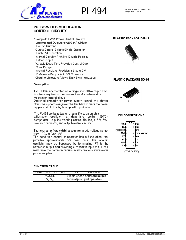
PLASTIC PACKAGE DIP-16 PLASTIC PACKAGE SO-16
The PL494 incorporates on a single monolithic chip all the functions required in the construction of a pulse-widthmodulation control circuit. Designed primarily for power supply control, this device offers the systems engineer the flexibility to tailor the power supply control circuitry to a specific application.
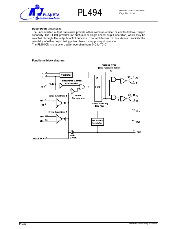
The PL494 contains two error amplifiers, an on-chip adjustable oscillator, a dead-time control (DTC) parator , a pulse-steering control flip-flop, a 5-V, 5%precision regulator, and output-control circuits.
PIN CONNECTIONS
The error amplifiers exhibit a mon-mode voltage range from
- 0.3V to Vcc
- 2V. The dead-time control parator has a fixed offset that provides approximately 5% dead time. The on-chip oscillator may be bypassed by terminating RT to the reference output and providing a sawtooth input to CT, or it may drive the mon circuits in synchronous multiple-rail power supplies.
(TOP VIEW)
FUNCTION TABLE
INPUT TO OUTPUT CTRL
OUTPUT FUNCTION
VI=GND VI=Vref
Single-ended or parallel output Normal push-pull operation
PL494
PAIHAUNG Product Specification
PL494
Revised Date : 2007/11/20 Page No. : 2/14
Description (continued) The unmitted output transistors provide either mon-emitter or...