G3VM-351A/D
MOS FET Relays
General-purpose Series with 350-V Load
Voltage.
• Upgraded G3VM-2 Series.
• Continuous load current of 120 mA.
• Operating time of 0.3 ms (typical).
RoHS compliant
■ Application Examples
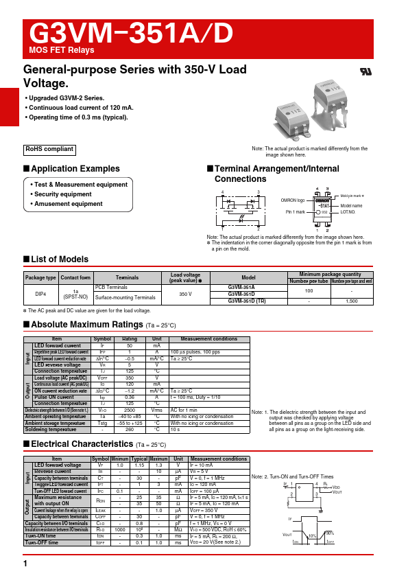
• Test & Measurement equipment
• Security equipment
• Amusement equipment
Note: The actual product is marked differently from the
image shown here.
■ Terminal Arrangement/Internal
Connections
43
OMRON logo
Mold pin mark *
Model name
Pin 1 mark
932 LOT.NO.
■ List of Models
12
Note: The actual product is marked differently from the image shown here.
* The indentation in the corner diagonally opposite from the pin 1 mark is from
a pin on the mold.
Package type Contact form
Terminals
DIP4
1a
(SPST-NO)
PCB Terminals
Surface-mounting Terminals
Load voltage
(peak value) *
350 V
* The AC peak and DC value are given for the load voltage.
■ Absolute Maximum Ratings (Ta = 25°C)
Model
G3VM-351A
G3VM-351D
G3VM-351D (TR)
Minimum package quantity
Number per tube Number per tape and reel
100 -
- 1,500
Item
LED forward current
Repetitive peak LED forward current
LED forward current reduction rate
LED reverse voltage
Connection temperature
Load voltage (AC peak/DC)
Continuous load current (AC peak/DC)
ON current reduction rate
Pulse ON current
Connection temperature
Dielectric strength between I/O (See note 1.)
Ambient operating temperature
Ambient storage temperature
Soldering temperature
Symbol
IF
IFP
ΔIF/°C
VR
TJ
VOFF
IO
ΔIO/°C
Iop
TJ
VI-O
Ta
Tstg
-
Rating
50
1
−0.5
5
125
350
120
−1.2
0.36
125
2500
−40 to +85
−55 to +125
260
Unit
mA
A
mA/°C
V
°C
V
mA
mA/°C
A
°C
Vrms
°C
°C
°C
Measurement conditions
100 μs pulses, 100 pps
Ta ≥ 25°C
Ta ≥ 25°C
t = 100 ms, Duty = 1/10
AC for 1 min
With no icing or condensation
10 s
■ Electrical Characteristics (Ta = 25°C)
Note: 1. The dielectric strength between the input and
output was checked by applying voltage
between all pins as a group on the LED side and
all pins as a group on the light-receiving side.
Item
Symbol Minimum Typical Maximum
LED forward voltage
VF 1.0 1.15 1.3
Reverse current
IR -
- 10
Capacity between terminals CT - 30 -
Trigger LED forward current IFT
-
1
3
Turn-OFF LED forward current IFC
0.1
-
-
Maximum resistance
with output ON
RON
-
-
25 35
35 50
Current leakage when the relay is open ILEAK
-
- 1.0
Capacity between terminals COFF
-
30
-
Capacity between I/O terminals CI-O - 0.8 -
Insulation resistance between I/O terminals RI-O 1000 108
-
Turn-ON time
tON - 0.3 1.0
Turn-OFF time
tOFF - 0.1 1.0
Unit
V
μA
pF
mA
mA
Ω
Ω
μA
pF
pF
MΩ
ms
ms
Measurement conditions
IF = 10 mA
VR = 5 V
V = 0, f = 1 MHz
IO = 120 mA
IOFF = 100 μA
IF = 5 mA, IO = 120 mA, t<1 s
IF = 5 mA, IO = 120 mA
VOFF = 350 V
V = 0, f = 1 MHz
f = 1 MHz, VS = 0 V
VI-O = 500 VDC, ROH ≤ 60%
IF = 5 mA, RL = 200 Ω,
VDD = 20 V(See note 2.)
Note: 2. Turn-ON and Turn-OFF Times
IF 1
2
4 RL
VDD
3 VOUT
IF
VOUT
tON
10%
90%
tOFF
1